Supercharge Your Innovation With Domain-Expert AI Agents!

LCOS projection optical structure

A technology of projection optics and polarized light, which is applied in the field of projectors, can solve the problems of low light efficiency and achieve the effect of improving energy utilization

Pending Publication Date: 2022-02-01
HENAN COSTAR GRP CO LTD +1
View PDF8 Cites 1 Cited by
  • Summary
  • Abstract
  • Description
  • Claims
  • Application Information

AI Technical Summary

Problems solved by technology

Therefore, none of the existing miniature LCOS projections adopts the PCS polarized light structure. Although the structure without PCS polarized light has advantages in volume, it can only use half of the polarization state light in the light source, and the overall light efficiency of the system is low.

Method used


Image

  • LCOS projection optical structure
  • LCOS projection optical structure
  • LCOS projection optical structure

Examples


Embodiment Construction

[0018] The present invention will be described in further detail below in combination with specific embodiments and with reference to the accompanying drawings.

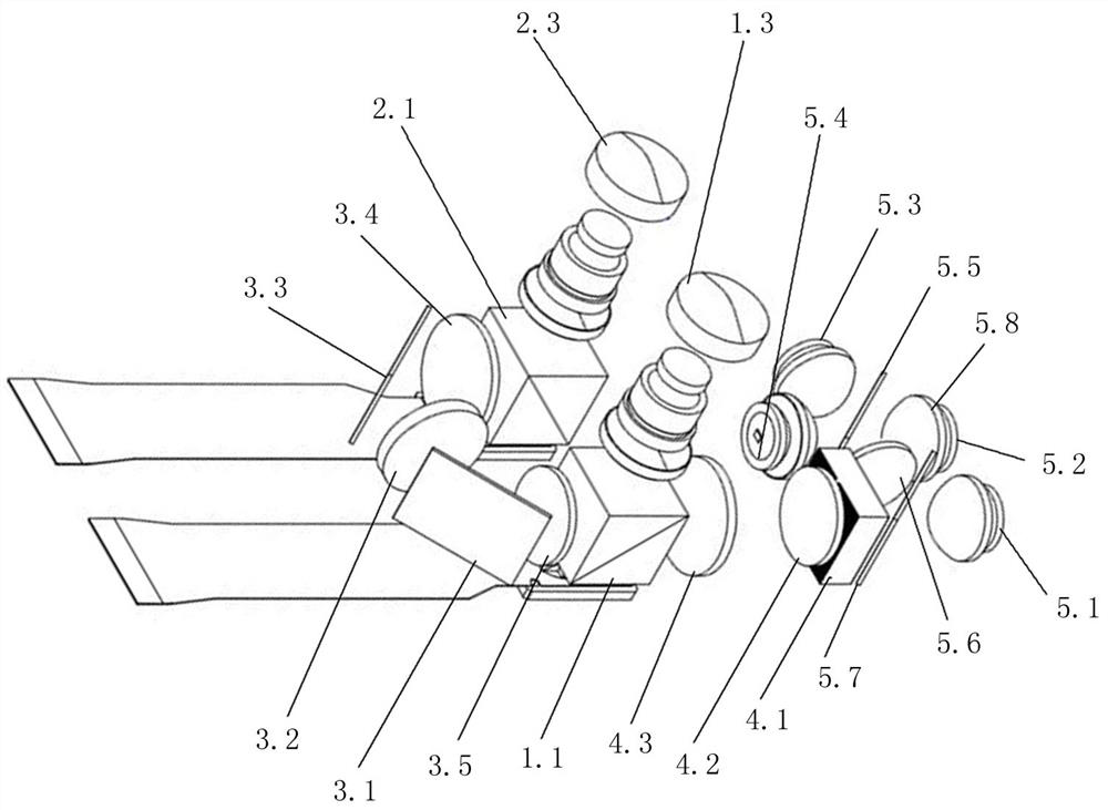
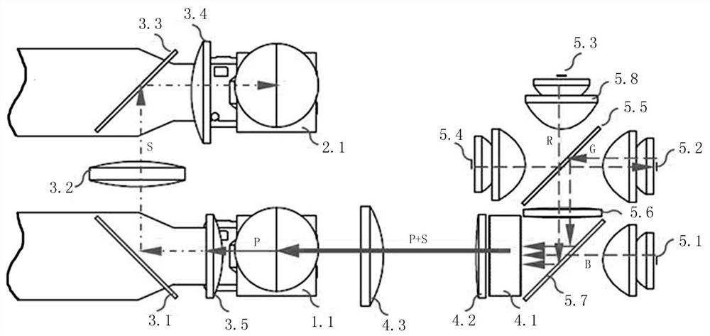
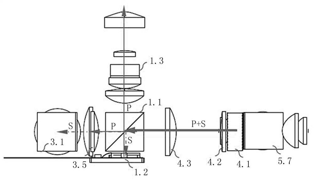
[0019] refer to Figure 1-4 As shown, an LCOS projection optical structure includes: a light source assembly, a first PBS1.1, a first LCOS imaging chip 1.2, a first imaging lens 1.3, a second PBS2.1, a second LCOS imaging chip 2.2 and a second imaging Lens 2.3;

[0020] The first PBS is located between the first LCOS imaging chip and the first imaging lens, and the first PBS is coaxially arranged with the light source assembly; the second PBS is located between the second LCOS imaging chip and the second imaging lens, and the second PBS and First PBS parallel setup;

[0021] Between the first PBS and the second PBS, a polarization conversion assembly, a first reflector 3.1, a fourth relay lens 3.2, a second reflector 3.3 and a fifth relay lens 3.4 are sequentially arranged along the optical path;

[0022] The firs...


PUM


Abstract

The invention discloses an LCOS projection optical structure. According to the LCOS projection optical structure, a double-LCOS imaging chip and double-lens light path structure is adopted. The LCOS projection optical structure specifically comprises a light source assembly, a first PBS, a first LCOS imaging chip, a first imaging lens, a second PBS, a second LCOS imaging chip and a second imaging lens; the first PBS transmits P polarized light and reflects S polarized light; the S polarized light enters the first LCOS imaging chip to be converted into the P polarized light, and then theP polarized light is reflected; the reflected P polarized light enters the first imaging lens through the first PBS to be imaged on a screen; the P polarized light transmitted by the first PBS is converted into S polarized light through a polarized light conversion assembly and then enters the second PBS, the second PBS reflects the S polarized light to the second LCOS imaging chip, the S polarized light is converted into P polarized light, and the P polarized light is reflected, and the reflected P polarized light enters the second imaging lens through the second PBS and is imaged on a screen; an imaging picture of the first imaging lens and an imaging picture of the second imaging lens coincide on the screen, and a highlight picture is output. According to the LCOS projection optical structure, light of the light source is fully utilized, so that light output of the system is improved.

Description

technical field [0001] The invention relates to the technical field of projectors, in particular to an LCOS projection optical structure. Background technique [0002] At present, micro-LCOS projectors usually use a single-chip LCOS chip, cooperate with LED light sources to synthesize color images through timing control, and output images through the lens. The polarization conversion efficiency of the PCS polarization conversion component applied to the traditional 3LCOS projector and the multiplication of the etendue of the system have no advantage over the optical efficiency without PCS polarization, and the optical machine volume becomes larger. Therefore, none of the existing micro-LCOS projections adopts the PCS polarized light structure. Although the structure without PCS polarized light has advantages in volume, it can only use half of the polarization state light in the light source, and the overall light efficiency of the system is low. Contents of the invention ...

Claims


Application Information

Patent Timeline
IPC IPC(8): G03B21/14G02B30/25G02B27/28G09F19/18
CPCG03B21/142G02B30/25G02B27/283G02B27/286G09F19/18
Inventor 章杰孙旭涛吴景淼孙中尚
Owner HENAN COSTAR GRP CO LTD
Features
  • R&D
  • Intellectual Property
  • Life Sciences
  • Materials
  • Tech Scout
  • Unparalleled Data Quality
  • Higher Quality Content
  • 60% Fewer Hallucinations
Learn More