Assembled and combined type new energy battery pack

A new energy, battery pack technology, applied in battery pack components, batteries, secondary batteries, etc., can solve problems such as resource waste, save resources, improve maintenance efficiency, and reduce maintenance costs.

Active Publication Date: 2022-02-01
深圳市创都科技有限公司
View PDF6 Cites 2 Cited by
  • Summary
  • Abstract
  • Description
  • Claims
  • Application Information

AI Technical Summary

Problems solved by technology

[0004] The existing new energy battery pack is composed of multiple sets of batteries connected in series or in parallel, and the outside is protected by heat shrinkable film; during the use of the new energy battery pack, battery damage will inevitably occur. During maintenance, in order to ensure The power supply of the battery pack is stable, and the maintenance is convenient. Most of them need to replace the entire battery pack, resulting in a great waste of resources.

Method used


Image

  • Assembled and combined type new energy battery pack
  • Assembled and combined type new energy battery pack
  • Assembled and combined type new energy battery pack

Examples


Embodiment 1

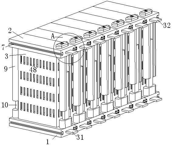
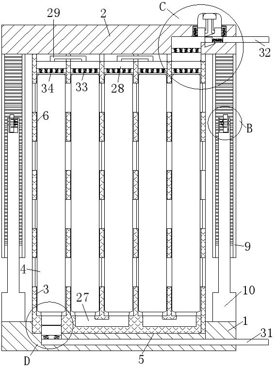
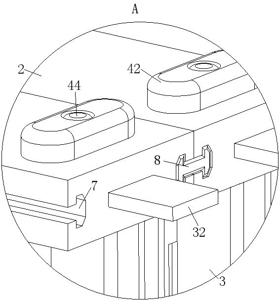
[0035] Such as Figure 1 to Figure 3 As shown, an assembled and combined new energy battery pack described in the embodiment of the present invention includes a base 1, a top base 2, a housing 3 and a battery 4; the top surface of the base 1 is provided with an installation groove 5, and the installation The inside of the groove 5 is plugged with the casing 3, and the top surface of the casing 3 is provided with a plurality of battery holes 6, and the battery 4 is slidably installed inside the battery hole 6, and the top seat 2 is installed on the top surface of the casing 3, Both sides of the base 1 and both sides of the top seat 2 are provided with connecting grooves 7, and the inside of the connecting grooves 7 on both sides are slide-mounted pins 8, and the top surfaces on both sides of the base 1 and the both sides of the top seat 2 There is a fixed structure between the bottom surfaces; when in use, install the battery 4 into the battery hole 6, then install the housing ...

Embodiment 2

[0045] Such as Figure 12 As shown in Comparative Example 1, another embodiment of the present invention is: the two sides of the installation groove 5 are provided with a buckle structure, and the buckle structure includes a convex buckle 53 and a No. 3 spring 54; Both sides of mounting groove 5 are provided with draw-in groove 52, and the inside of described draw-in groove 52 slides and installs convex button 53, and the inner wall of described draw-in groove 52 is affixed to one end of No. 3 spring 54, and the other end of No. 3 spring 54 is fixed. One end is fixedly connected with the convex buckle 53, and both sides of the bottom of the housing 3 are provided with fixing holes 55, and the convex buckle 53 is slidably matched with the fixing hole 55; when in use, when the housing 3 is inserted into the installation groove 5, the convex buckle 53 is squeezed by the side wall of the housing 3 and slides into the slot 52, so that the No. 3 spring 54 is compressed. When the co...


PUM


Abstract

The invention belongs to the field of new energy, and particularly relates to an assembled and combined type new energy battery pack. The assembled and combined type new energy battery pack comprises a base, a top seat, a shell and batteries, wherein a mounting groove is formed in the top surface of the base, a shell is inserted into the mounting groove, a plurality of battery holes are formed in the top surface of the shell, the batteries are slidably mounted in the battery holes, the top seat is mounted on the top surface of the shell, connecting grooves are formed in the two sides of the base and the two sides of the top seat, pin rods are slidably mounted in the connecting grooves in the two sides, and fixing structures are arranged between the top faces of the two sides of the base and the bottom faces of the two sides of the top base. The batteries are installed in the battery holes, the fixing structures are used for driving the top seat and the base to fix and lock the shell to form an independent battery module, and the pin rods are used for penetrating into the connecting grooves, thereby forming the battery pack; and when a battery is damaged, a single battery module is replaced in order to ensure the power supply stability of the battery pack, so maintenance personnel can conveniently replace and maintain the battery, maintenance cost is reduced, and resources are saved.

Description

technical field [0001] The invention belongs to the field of new energy, in particular to an assembled and combined new energy battery pack. Background technique [0002] New energy refers to renewable resources developed and utilized on the basis of new technology and technology. With the limitations of conventional energy and environmental problems becoming increasingly prominent, people are gradually inclined to use new energy; especially in the electric vehicle industry, It is gradually changing from gasoline kinetic energy to electric kinetic energy, thus creating a new energy battery to power the vehicle. [0003] A Chinese patent with the publication number CN112259817B discloses a new energy battery pack, including a chassis and a support plate, and the chassis and the support plate are provided with a rotating device, a clamping device, a displacement device, a vertical displacement device, a detection device, quantification device and transmission device; one side...

Claims


Application Information

Patent Timeline
Patent Type & Authority Applications(China)
IPC IPC(8): H01M50/244H01M50/213H01M50/264H01M50/258H01M50/242H01M50/51H01M50/512H01M50/572H01M10/48H01M10/613H01M10/625H01M10/6556
CPCH01M50/244H01M50/213H01M50/264H01M50/258H01M50/242H01M50/51H01M50/512H01M50/572H01M10/488H01M10/613H01M10/625H01M10/6556H01M2220/20Y02E60/10
Inventor 陈灿
Owner 深圳市创都科技有限公司
Why Eureka
Try Eureka