Power-on reset circuit and related reset method

a power-on reset and circuit technology, applied in pulse manipulation, pulse technique, instruments, etc., can solve the problems of improper reset, less accurate por circuit, and more likely malfunction of por circuit internal components, so as to ensure the stability of power supply voltage and reduce power consumption.

Active Publication Date: 2020-03-31
ARTERY TECH CO LTD
View PDF2 Cites 1 Cited by
  • Summary
  • Abstract
  • Description
  • Claims
  • Application Information

AI Technical Summary

Benefits of technology

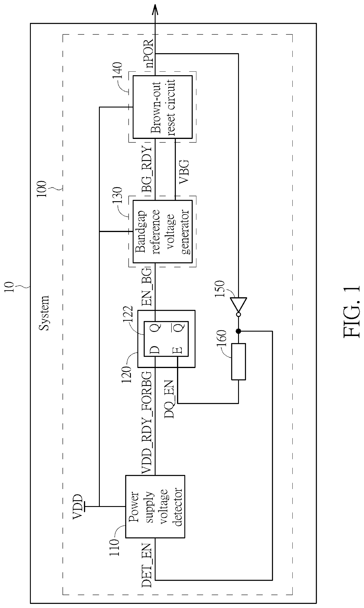
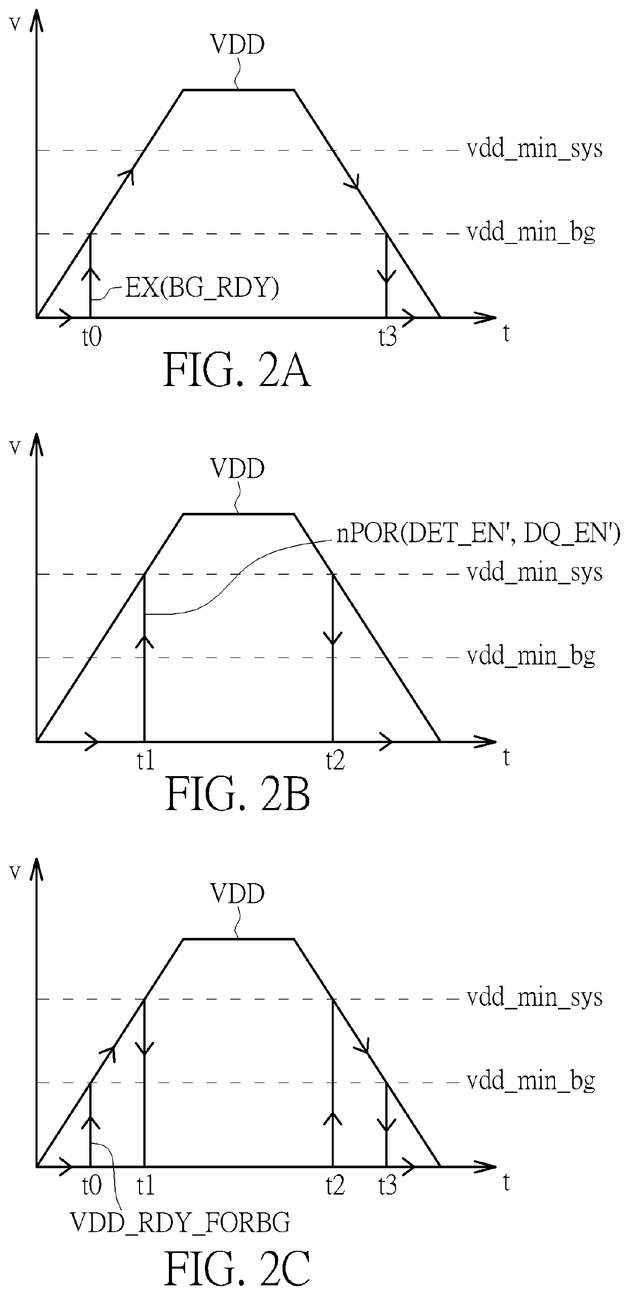
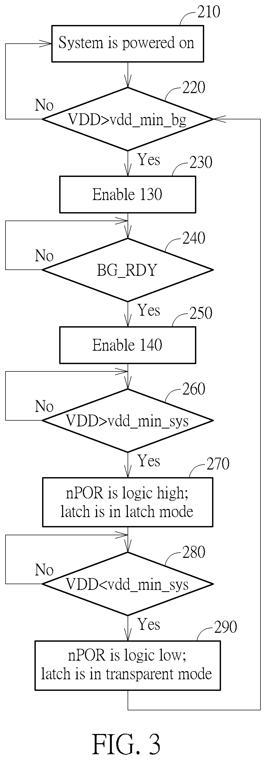
[0003]It is an object of the present invention to provide an innovative architecture of a PoR circuit. The PoR circuit of the present invention comprises a power supply voltage detector, which is provided to ensure stability of a power supply voltage, thereby ensuring reliability of a reference voltage generator in the PoR circuit. In addition, the architecture of the PoR circuit of the present invention also includes a holding circuit for maintaining detection results outputted by the power supply voltage detector. Under certain conditions, the power supply voltage detector can be disabled / shut down to reduce power consumption. The holding circuit can keep driving the reference voltage generator by using the detection result, such that the PoR circuit of the present invention can still operate properly even if the power supply voltage detector is shut down.

Problems solved by technology

However, such PoR circuit is less accurate.
This may eventually lead to improper resets.
However, due to its complicated architecture, internal components of the PoR circuit are more likely to malfunction due to complicated interactions between components, especially the bandgap reference voltage circuit.
The bandgap reference voltage circuit may be affected by the power supply voltage and thus output an inaccurate reference voltage.
Therefore, such type of the PoR circuit will face reliability issues.

Method used


Image

  • Power-on reset circuit and related reset method
  • Power-on reset circuit and related reset method
  • Power-on reset circuit and related reset method

Examples


Embodiment Construction

[0013]In the following description, numerous specific details are set forth to provide a thorough understanding of embodiments of the invention. One skilled in the relevant art will recognize, however, that the invention can be practiced without one or more of the specific details, or with other methods, components, materials, etc. In other instances, well-known structures, materials, or operations are not shown or described in detail to avoid obscuring aspects of the invention.

[0014]Reference throughout this specification to “one embodiment” or “an embodiment” means that a particular feature, structure, or characteristic described in connection with the embodiment is included in at least one embodiment of the present invention. Thus, the appearances of the phrases “in one embodiment” or “in an embodiment” in various places throughout this specification are not necessarily all referring to the same embodiment. Furthermore, the particular features, structures, or characteristics may ...


PUM


Abstract

A power-on reset circuit arranged to generate a reset signal according to a power supply voltage includes: a power supply voltage detector, a holding circuit, a reference voltage generator and a reset determination circuit. The power supply voltage detector is controllable by the reset signal, and arranged to detect a level of the power supply voltage to generate a detection signal. The holding circuit is arranged to output an enablement signal according to the detection signal, wherein the holding circuit selectively maintains a level of the enablement signal according to a level of the detection signal. The reference voltage generator is controllable by the enablement signal to selectively output a reference voltage. The reset determination circuit is arranged to output the reset signal according to the power supply voltage and the reference voltage.

Description

BACKGROUND OF THE INVENTION1. Field of the Invention[0001]The present invention relates generally to power-on reset, and more particularly, to a power-on reset circuit having a power supply voltage detector and related reset method.2. Description of the Prior Art[0002]Typically, a power-on reset (PoR) circuit is provided in an integrated circuit to generate a reset signal for reset circuit components in the integrated circuit. The purpose of the PoR circuit is to ensure various circuit components in the integrated circuit can be placed in a known state at the beginning of operation. In the conventional art, there are two different types of the PoR circuits, one of which is based on the threshold voltage Vt of MOS transistors, while the other of which is based on a bandgap voltage reference. The advantage of the PoR circuit based on the threshold voltage Vt is simplicity and stability. However, such PoR circuit is less accurate. This is because the threshold voltage Vt often drifts w...

Claims


Application Information

Patent Timeline
Patent Type & Authority Patents(United States)
IPC IPC(8): H03L7/00H03K17/22G06F1/24H03K5/01G05F1/46H03K3/037H03K5/00
CPCG05F1/461H03K3/037H03K5/01H03K2005/00078H03K17/22H03K3/0375
Inventor WANG, ZHENGXIANGHUANG, CHEN-CHUNLIN, HUNG-YU
Owner ARTERY TECH CO LTD
Why Eureka
Try Eureka