
Bearing motor

A bearing motor and inner bearing technology, which is applied in the direction of electrical components, electromechanical devices, electric components, etc., can solve problems such as lack of strong support from back-end equipment manufacturers, and achieve obvious energy-saving effects, increase startup speed, and extend battery life.

Pending Publication Date: 2022-02-01
武思军
View PDF0 Cites 0 Cited by
  • Summary
  • Abstract
  • Description
  • Claims
  • Application Information

AI Technical Summary

Problems solved by technology

Although the high-voltage DC power supply can choose a variety of voltages, there is still no strong support from back-end equipment manufacturers

Method used


Image

  • Bearing motor
  • Bearing motor
  • Bearing motor

Examples


Embodiment Construction

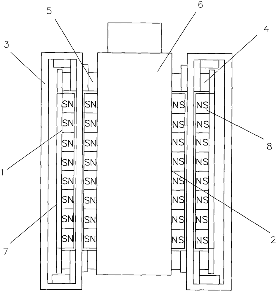
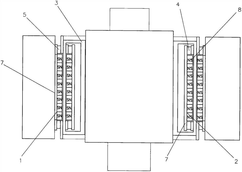
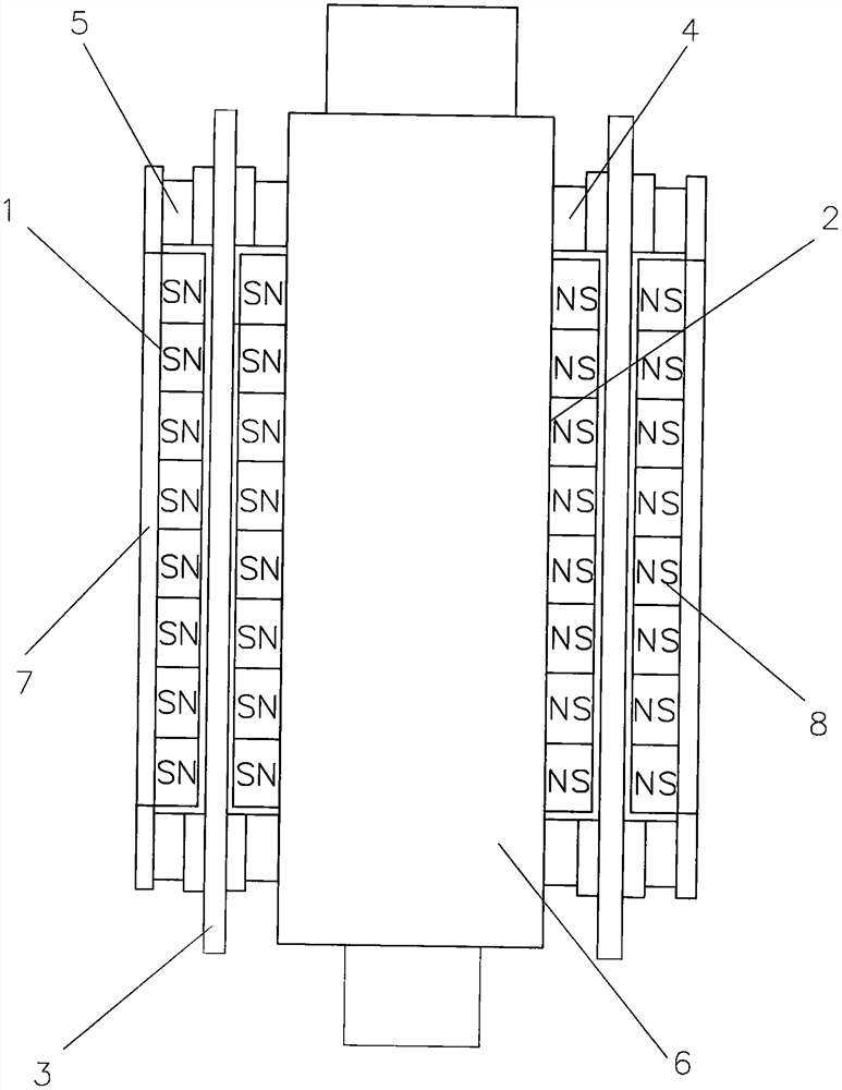
[0033] Implementation column 1, such as figure 1 and Figure 4 As shown in: a bearing motor, including an outer rotor 1, an inner rotor 2, a wire 3, an inner bearing 4 and an outer bearing 5, it is characterized in that: in the cavity of the outer rotor 1, an inner rotor 2 is arranged, and the outer The rotor 1 and the inner rotor 2 are coaxial, the outer rotor 1 and the inner rotor 2 are both magnets, and there is a certain gap between the inner wall of the outer rotor 1 and the outer wall of the inner rotor 2 Magnetic cavity, the magnetic cavity is a uniform centripetal magnetic field, the outer rotor 1 is a magnet composed of several permanent magnets with the same radial magnetic field arranged on the inner wall of the circular iron cylinder 7, the permanent magnet 8 The magnetic field placement directions are all radial N-S, or all radial S-N, and the inner rotor 2 is cylindrical, and the inner rotor is arranged on the outer surface of the circular iron rod 6. Magnets c...


PUM


Abstract

The invention relates to a bearing motor. In order to improve the energy efficiency, the rotating speed and the power-to-weight ratio of the direct-current motor and prolong the service life of the direct-current motor, because of the defect that the direct-current motor actually needs to change an electromagnetic field, the invention ingeniously realizes that a magnetic pole is kept unchanged in the rotating direction by applying the Ampere law principle and combining the structural characteristics of a bearing, and realizes brushless, coreless and transformation magnetic field-free and transformation current-free effects; therefore, the direct current motor is a real direct current motor. According to the technical scheme, an inner rotor is arranged in a cavity of a cylindrical outer rotor, an inner bearing and an outer bearing are arranged between the two ends of the outer rotor and the two ends of the inner rotor, the bearings support the outer rotor and the inner rotor, a certain gap is kept between the outer rotor and the inner rotor without contact, and the outer rotor and the inner rotor are both magnets. A certain gap is formed between the inner wall of the outer rotor and the outer wall of the inner rotor to form a magnetic cavity, a wire axially penetrates through the magnetic cavity to cut magnetic lines of force, the outer ring of the inner bearing and the inner ring of the outer bearing are tightly connected with the wire and are fixed, and the outer rotor and the inner rotor synchronously rotate.

Description

technical field [0001] The invention relates to a motor, especially a DC motor combined with the structural features of a bearing. Background technique [0002] Various existing DC motors, such as brushed DC motors and brushless DC motors, are not DC motors in the true sense. These so-called DC motors only have DC input or output current, and the output current is not stable. The internal magnetoelectric working process and working principle of DC motors and brushless DC motors are AC electromagnetic fields, so these so-called DC motors still have the iron loss and copper loss that must exist in the transformer. Due to the existence of iron loss and copper loss, As a result, brushed DC motors and brushless DC motors lose a lot of energy when they rotate at high speeds, and they generate serious heat, so it is difficult to operate at ultra-high speeds. Now all motors and DC motors are developed based on the Faraday armature. The working principle of the DC generator is to us...

Claims


Application Information

Patent Timeline
Patent Type & Authority Applications(China)
IPC IPC(8): H02K16/02H02K1/276H02K1/279H02K5/167H02K5/173H02K3/28
CPCH02K16/02H02K1/276H02K1/2786H02K5/1672H02K5/1732H02K3/28H02K2213/03
Inventor 武思军
Owner 武思军
Learn More