Discharge apparatus

A discharge device, installation state technology, applied in the direction of injection device, distribution device, liquid injection device, etc., to achieve the effect of stable installation state, suppression of original liquid leakage, and simple structure

Active Publication Date: 2022-02-01
DAIZO
View PDF14 Cites 0 Cited by
  • Summary
  • Abstract
  • Description
  • Claims
  • Application Information

AI Technical Summary

Problems solved by technology

Therefore, it becomes possible to remove the discharge member from the container after all the stock solution has been discharged and replace it with a new container.

Method used


Image

  • Discharge apparatus
  • Discharge apparatus
  • Discharge apparatus

Examples


Embodiment Construction

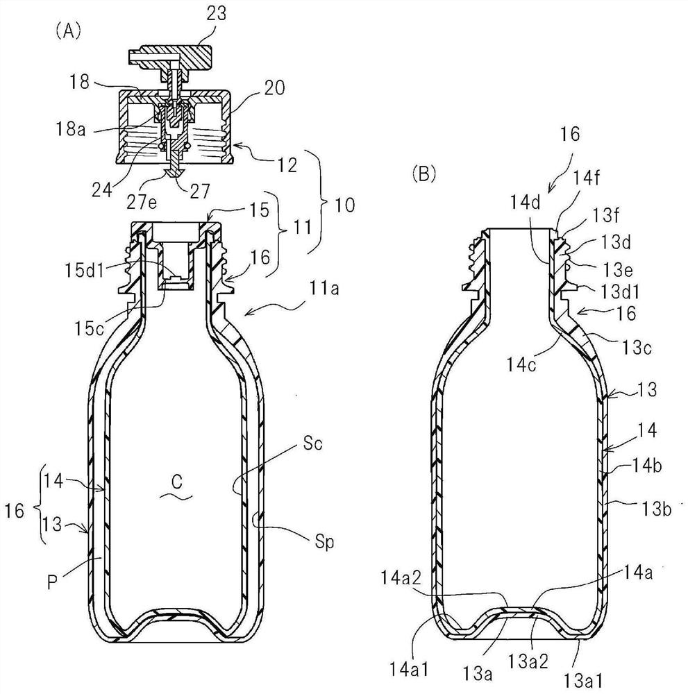
[0076] figure 1 The discharge device 10 shown in (A) is composed of a double pressurized container (container) 11 , a discharge member 12 , an undiluted solution (content) C and a pressurizing agent P filled in the double pressurized container 11 . The product filled with the undiluted solution C and the pressurizing agent P in the double pressurized container 11 is the pressurized product 11a. The pressurized product 11a and the discharge part 12 are pre-assembled as a complete set (refer to figure 1 (A)), or half-assembled in an unopened state (see image 3 (A)) for sale. The pressurized product 11a may be sold separately as a replacement instead of being sold together with the discharge member 12 . Therefore, the pressurized product 11a is hermetically sealed before the discharge member 12 is attached (unsealed by the discharge member 12) to prevent leakage of the filled stock solution C or pressurizing agent P. The discharge member 12 may also be sold separately.

[0...


PUM


Abstract

Provided is a discharge apparatus capable of suppressing leakage of raw fluid caused by removal of a valve. The discharge apparatus comprises: a pressurized product 11a having a raw fluid C and a pressurizing agent P filled inside a container 10 and sealed; and a discharge member 12 that pierces the pressurized product 11a and discharges the raw fluid C. The discharge member 12 comprises: a valve 21 that forms the discharge passage for the raw fluid C; and a cap 20 that covers the valve 21 and is detachably attached to the pressurized product 11a. The discharge member comprises suppression means (a support mechanism K, movable lids 81, 91, and a mechanism Re that presses and partially releases a protruding section 520a towards the bottom 513d of a recess 513b) that suppress leakage of the raw fluid C caused by removal of the valve 21.

Description

technical field [0001] The invention relates to discharge devices. In particular, it relates to a discharge device including a container for filling and sealing a container for a pressurized product and a discharge member that is detachable from the pressurized product. Background technique [0002] Patent Document 1 describes a discharge device configured by attaching a discharge member including a valve to a container filled with an undiluted solution and a pressurizing agent. In this discharge device, the discharge member is detachable from the container. Specifically, the discharge member includes a valve and a cap that covers the valve. Then, the discharge member is attached to the container by screwing the cap to the screw provided on the outer periphery of the neck of the container. Therefore, it is possible to reuse the discharge member by removing the discharge member from the container and replacing it with a new container after all the stock solution has been d...

Claims


Application Information

Patent Timeline
Patent Type & Authority Applications(China)
IPC IPC(8): B05B9/04B65D1/02B65D83/38B65D83/62
CPCB65D83/62B65D83/382B65D83/20B65D83/206B65D83/48B65D83/66
Inventor 菅原信也片冈公雄宫本英俊
Owner DAIZO
Why Eureka
Try Eureka