Communication equipment and method

A technology of communication equipment and addressing equipment, which is applied in image communication, pulse modulation TV signal transmission, data exchange through path configuration, etc. It can solve the problem of inability to transmit broadcast packets and achieve the effect of easy communication

Inactive Publication Date: 2004-02-25
SONY CORP
View PDF0 Cites 0 Cited by
  • Summary
  • Abstract
  • Description
  • Claims
  • Application Information

AI Technical Summary

Problems solved by technology

However, since the router 1 itself cannot transmit broadcast packets, it is necessary to provide a specific function such as a gateway function for each use case including service discovery, and the user must specify predetermined settings for each function

Method used


Image

  • Communication equipment and method
  • Communication equipment and method
  • Communication equipment and method

Examples


Embodiment Construction

[0048] Next, preferred embodiments of the present invention will be described in detail.

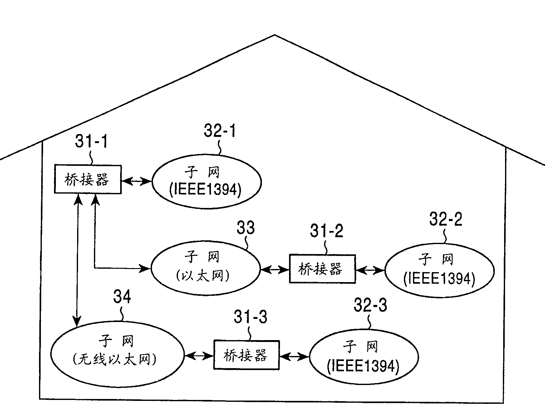
[0049] image 3 is a diagram illustrating a network according to the present invention. The bridge 31-1 is connected to the IEEE-1394 subnet 32-1 based on the IEEE-1394 configuration, the Ethernet subnet 33 based on the Ethernet configuration, and the wireless Ethernet subnet 34 based on the wireless Ethernet configuration.

[0050] The bridge 31-1 receives a packet from a unit connected to the IEEE-1394 subnet 32-1, converts it into a packet in a predetermined manner, and sends the packet to the Ethernet subnet 33 connected to or the wireless Ethernet subnet 34 for a predetermined unit. The bridge 31-1 receives a packet from a unit connected to the Ethernet subnet 33 or the wireless Ethernet subnet 34, converts it into a packet of a predetermined pattern, and sends the packet to a unit connected to the IEEE-1394 subnet 32- 1 for a predetermined unit.

[0051] The bridge 31-2 is conn...


PUM


Abstract

In a communication technique allowing units connected to sub-nets (32-2,33) to communicate with each other, a CPU (51) generates the offset corresponding to an MAC address. A memory (52) stores the generated offset correspondingly to the MAC address. An IEEE-1394 interface (55) generates an IEEE-1394 packet which includes the generated offset.

Description

technical field [0001] The present invention relates to a communication device and method, and more particularly to a communication device and a communication method that allow units connected to subnets in different ways to easily communicate with each other. Background technique [0002] figure 1 is a diagram illustrating a conventional home network. Router 1 is connected to each subnet: Ethernet (Ethernet (is its trade name)) subnet 2, IEEE (Institute of Electrical and Electronic Engineers, Institute of Electrical and Electronic Engineers) 1394 subnet 3, telephone line (twisted pair cable) A subnetwork 4 as transmission medium, a subnetwork 5 using power lines as transmission medium, the Internet 21, and a telephone line 22, which may be a digital subscriber line (DSL), such as a high data rate DSL (HDSL), Symmetric DSL (SDSL), Asymmetric DSL (ADSL), or Very High Data Rate DSL (VDSL). [0003] A personal computer (PC) 6-1 and a TV (television) unit 7-1 are connected to...

Claims


Application Information

Patent Timeline
IPC IPC(8): H04B3/54H04L12/28H04L12/40H04L12/46H04L29/06H04N7/24H04N21/436H04N21/4363
CPCH04L69/22H04L69/08H04N21/43632H04N21/43615H04L12/28
Inventor 藤泽谦二
Owner SONY CORP
Why Eureka
Try Eureka