Dust removal and desulfurization process for industrial waste gas

A technology for industrial waste gas and desulfurization process, applied in gas treatment, dispersed particle filtration, membrane technology, etc., can solve problems such as increasing treatment costs, polluting the atmospheric environment, and clogging the inner wall of pipelines, reducing treatment costs, improving treatment efficiency, Improve the effect of contact mixing

Pending Publication Date: 2022-02-08
成天洪
View PDF5 Cites 0 Cited by
  • Summary
  • Abstract
  • Description
  • Claims
  • Application Information

AI Technical Summary

Problems solved by technology

[0002] Industrial production generates a large amount of industrial waste gas. If it is not purified and discharged directly into the atmosphere, it will seriously pollute the atmosphere.
In the existing industrial waste gas treatment, because the industrial waste gas contains a large amount of smoke and dust, and the removal effect on the smoke is poor, a large amount of smoke and dust enter the desulfurization treatment liquid together with the industrial waste gas, and react with the desulfurization treatment liquid, which will quickly Consumption of desulfurization treatment liquid, on the one hand, it is necessary to continuously provide a large amount of desulfurization treatment liquid, which will increase the consumption of desulfurization treatment liquid, increase the treatment cost, and greatly reduce the treatment effect on industrial waste gas; on the other hand, due to the accumulation of smoke and dust It will cause blockage of the inner wall of the pipeline, reduce the treatment efficiency of industrial waste gas, and increase the difficulty of pipeline maintenance and repair. In view of this, we propose an industrial waste gas dedusting and desulfurization process

Method used


Image

  • Dust removal and desulfurization process for industrial waste gas
  • Dust removal and desulfurization process for industrial waste gas
  • Dust removal and desulfurization process for industrial waste gas

Examples


Embodiment Construction

[0024] The following will clearly and completely describe the technical solutions in the embodiments of the present invention with reference to the drawings in the embodiments of the present invention.

[0025] An industrial waste gas dedusting and desulfurization process is characterized in that it comprises the following steps:

[0026] S1. Design a waste gas dedusting and desulfurization device;

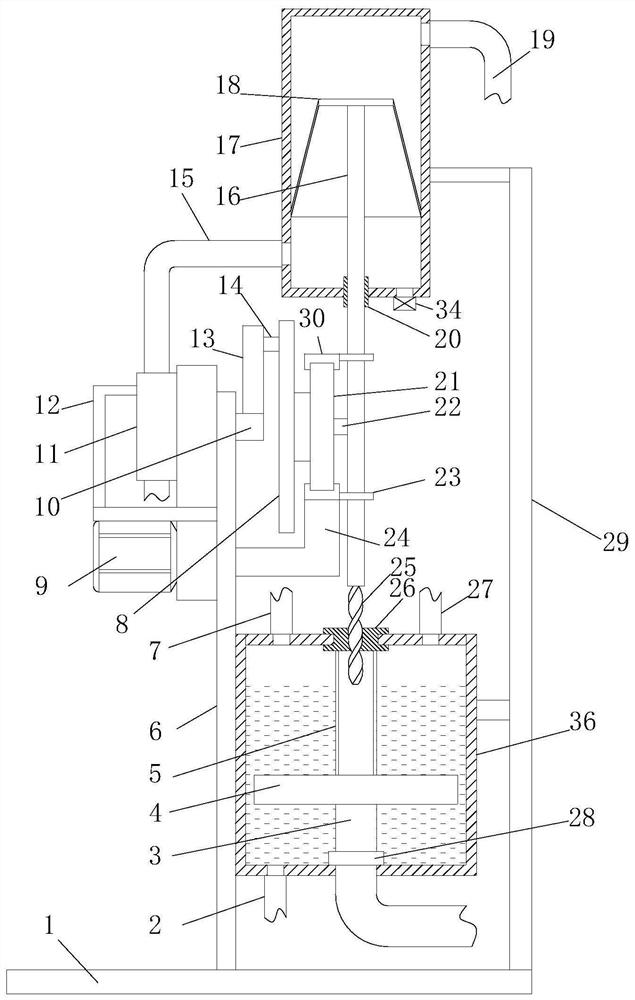
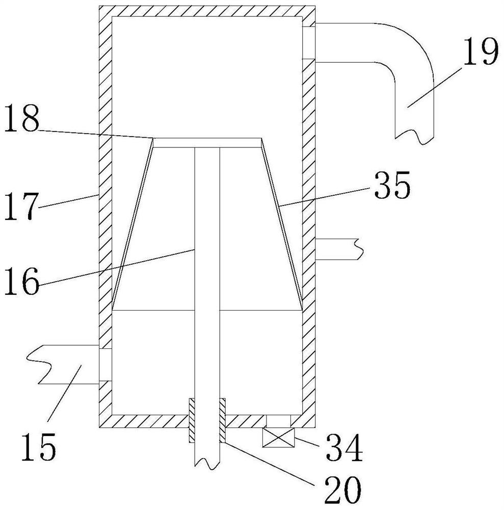
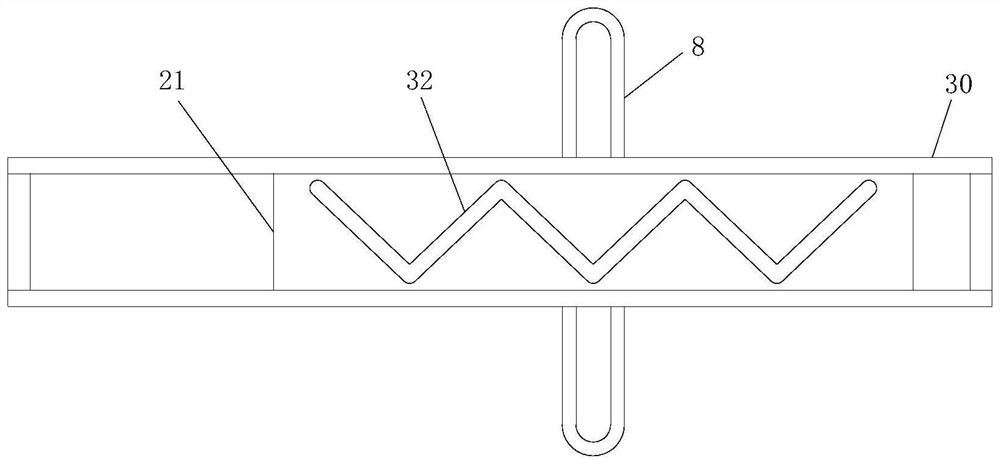
[0027] see Figure 1 to Figure 5 , an exhaust gas dedusting and desulfurization device includes a base 1, and also includes:

[0028] The pumping mechanism is used to convey industrial waste gas for dust removal and desulfurization treatment, and the pumping mechanism is arranged on the base 1;

[0029] The dust filter mechanism is used to remove dust from the industrial waste gas transported by the pump mechanism, and the dust filter mechanism can be automatically placed and blocked under the drive of the pump mechanism, and the dust filter mechanism is arranged on the base 1; ...


PUM


Abstract

The invention relates to a dust removal and desulfurization process for industrial waste gas. The dust removal and desulfurization process is characterized by comprising the following steps: S1, designing a waste gas dust removal and desulfurization device; S2, during working, starting a motor (9) of the waste gas dust removal and desulfurization device, allowing the motor to drive an impeller in a pump impeller (11) to rotate through a rotating shaft (10), so that the pump impeller conveys the industrial waste gas to be subjected to dust removal and desulfurization into a dust filtering mechanism through a second gas pipe (15) for dust removal treatment, and smoke dust in the industrial waste gas is removed before the industrial waste gas is subjected to desulfurization treatment; and S3, conveying the industrial waste gas subjected to smoke dust filtration into a sleeve (28) through a first gas pipe (19), conveying the industrial waste gas into a gas spraying pipe (4) through the sleeve, then spraying the industrial waste gas into desulfurization treatment liquid in a desulfurization cylinder (36) through small holes in the side wall of the gas spraying pipe to realize desulfurization treatment on the industrial waste gas, and conveying the industrial waste gas subjected to desulfurization treatment to a next treatment process through an exhaust pipe (7).

Description

technical field [0001] The invention relates to the field of industrial waste gas treatment equipment, in particular to an industrial waste gas dedusting and desulfurization process. Background technique [0002] Industrial production generates a large amount of industrial waste gas. If it is not purified and discharged directly into the atmosphere, it will seriously pollute the atmosphere. In the existing industrial waste gas treatment, because the industrial waste gas contains a large amount of smoke and dust, and the removal effect on the smoke is poor, a large amount of smoke and dust enter the desulfurization treatment liquid together with the industrial waste gas, and react with the desulfurization treatment liquid, which will quickly Consumption of desulfurization treatment liquid, on the one hand, it is necessary to continuously provide a large amount of desulfurization treatment liquid, which will increase the consumption of desulfurization treatment liquid, increas...

Claims


Application Information

Patent Timeline
Patent Type & Authority Applications(China)
IPC IPC(8): B01D53/48B01D53/78B01D46/02B01D46/04
CPCB01D46/02B01D46/04B01D53/78B01D53/48B01D2258/02
Inventor 成天洪
Owner 成天洪
Why Eureka
Try Eureka