
Eureka
For R&D, Eureka makes reading and utilizing patents & technical documents easy.
Eureka AIR
Designed for self-driven R&D workflows. Generate viable solutions, solve complex R&D challenges, empower your innovation with AI.

Eureka Materials
Designed for material experts only. Revolutionize your material R&D, from search, analyze, to developing new materials.

TechResearch
Generate reliable direction feasibility study reports for your R&D in just a few steps.

TechSeek
Discover and master advanced knowledge NOW. Basics, ideas, possibilities, all at once.

TechMind
As an expert in R&D Theories, TechMind can generates customized viable solutions instantly.

TechRisk
Analyze your overall solution with one click, know your potential R&D risks in advance.

TechMonitor
Get weekly tech updates, stay abreast of the latest tech innovations and key insights.
Maintenance device based on garden cement pavement construction
A technology for cement pavement and garden, applied in the direction of roads, roads, buildings, etc., can solve problems such as troublesome, troublesome connection rope retraction and fixation, etc., to achieve the effect of convenient retraction
- Summary
- Abstract
- Description
- Claims
- Application Information
AI Technical Summary
Problems solved by technology
Method used
Image

Examples
Embodiment 1
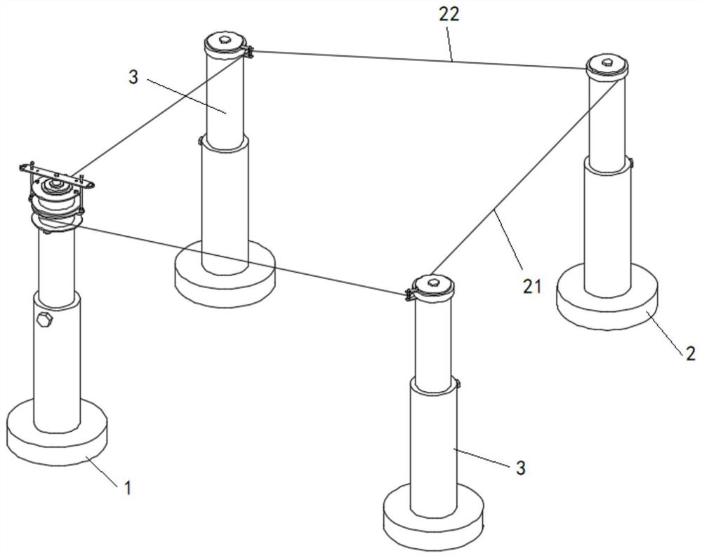
[0028] see Figures 1 to 8 As shown, the present invention is a maintenance device based on garden cement road construction, including a first pillar 1 and a second pillar 2; the top of the first pillar 1 is rotatably mounted with a first winding wheel 14 and a second winding wheel 15. The first winding wheel 14 and the second winding wheel 15 are respectively wound with a first winding rope 21 and a second winding rope 22, and the ends of the first winding rope 21 and the second winding rope 22 are fixed on the second winding rope. The end of the pillar 2 ; at least one third pillar 3 is connected to the first rope 21 and / or the second rope 22 between the first pillar 1 and the second pillar 2 .
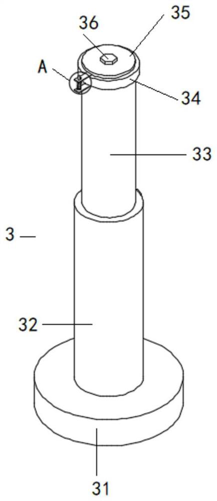
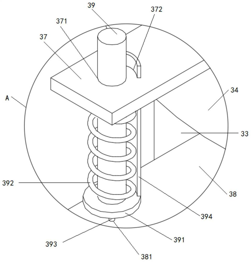
[0029] Both the second pillar 2 and the third pillar 3 include a second pillar body, the second pillar body includes a base A31, an outer sleeve A32 is arranged on the upper surface of the base A31, and an inner sleeve rod A33 is telescopically sleeved on the outer sleeve A32; The ...
Embodiment 2
[0032] Example 2, such as Figure 5 and 8As shown, in order to better control the rotation of the rotating operation panel 17, a bearing groove 16 is arranged on the top of the inner sleeve rod B12, and a bearing C161 is installed in the bearing groove 16, and a fixed column 162 is installed on the bearing C161. The end of 162 cooperates to install the rotating operation plate 17, and the positioning rod 18 with one end inserted into the first winding wheel 14 / second winding wheel 15 is arranged on the rotating operating plate 17; the first winding wheel 14 is provided with a pair of The bump C141, the upper surface of the bump C141 is provided with a positioning plug A142, and the blind hole A is arranged on the positioning plug A142; the upper surface of the second winding wheel 15 is provided with a pair of positioning plugs B151, and the positioning plug B151 is provided with a blind hole B: Both ends of the rotating operation plate 17 are respectively provided with a fir...
PUM
 Abstract
Description
Claims
Application Information
 - R&D Engineer
- R&D Manager
- IP Professional
- Industry Leading Data Capabilities
- Powerful AI technology
- Patent DNA Extraction
Browse by: Latest US Patents, China's latest patents, Technical Efficacy Thesaurus, Application Domain, Technology Topic, Popular Technical Reports.
© 2024 PatSnap. All rights reserved.Legal|Privacy policy|Modern Slavery Act Transparency Statement|Sitemap|About US| Contact US: help@patsnap.com