Crankshaft dynamic balancing machine

A dynamic balancing machine and crankshaft technology, which is applied in static/dynamic balance testing, machine/structural components testing, instruments, etc., can solve the problem of asymmetric weight distribution center, unbalance, and affecting three-cylinder crankshaft dynamic balance verification Accuracy and other issues to achieve the effect of improving accuracy and expanding the scope of application

Active Publication Date: 2022-02-08
上海剑平动平衡机制造有限公司
View PDF4 Cites 3 Cited by
  • Summary
  • Abstract
  • Description
  • Claims
  • Application Information

AI Technical Summary

Problems solved by technology

However, the weight distribution of the three-cylinder crankshaft is asymmetrical with respect to the center of its rotation axis. Since the inertial force takes a moment for the fulcrum, the directions of the two moments of inertia are the same, resulting in a non-zero resultant moment and an unbalanced moment.
When there is a gap in the fulcrum, it will swing, which will affect the accuracy of the dynamic balance calibration of the three-cylinder crankshaft

Method used


Image

  • Crankshaft dynamic balancing machine
  • Crankshaft dynamic balancing machine
  • Crankshaft dynamic balancing machine

Examples


Embodiment Construction

[0034] The following is attached Figure 1-8 The application is described in further detail.

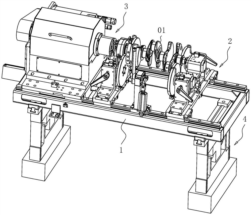
[0035] The embodiment of the application discloses a crankshaft dynamic balancing machine. refer to figure 1A crankshaft dynamic balancing machine includes a swing frame 1, a support mechanism 2 and a drive mechanism 3 are sequentially arranged above the swing frame 1, and a detection mechanism 4 is arranged at the bottom of the swing frame 1. When performing dynamic balance check on the three-cylinder crankshaft 01, place the three-cylinder crankshaft 01 on the support mechanism 2, use the support mechanism 2 to support it, and then use the drive mechanism 3 to drive the three-cylinder crankshaft 01 to rotate. During the rotation The detection mechanism 4 monitors the rotation state of the three-cylinder crankshaft 01, and performs a dynamic balance check on the three-cylinder crankshaft 01.

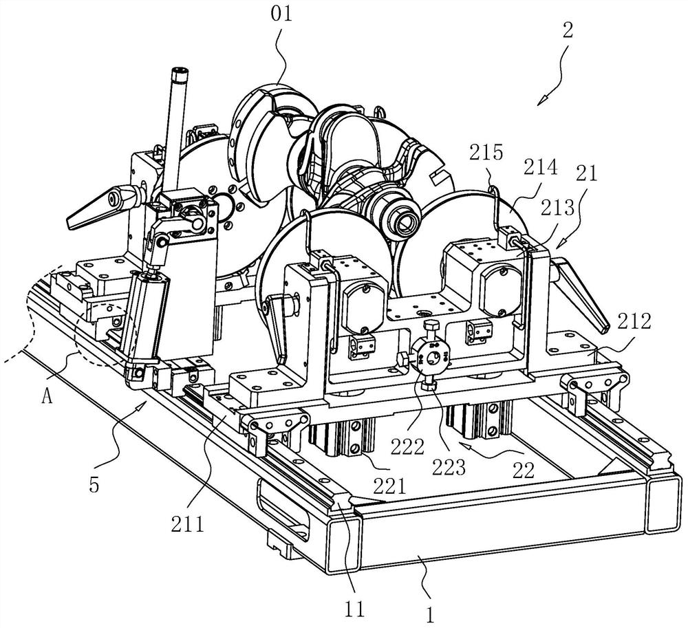
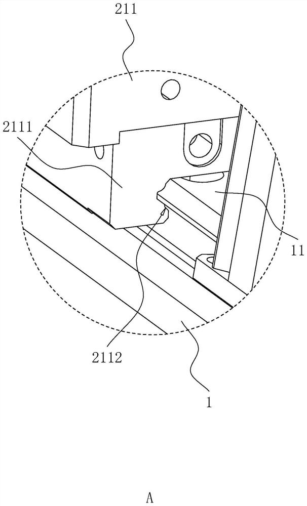
[0036] refer to figure 2 and image 3 , the support mechanism 2 includes two support...


PUM


Abstract

The invention relates to the field of dynamic balancing machines, and discloses a crankshaft dynamic balancing machine which comprises a swing frame, a supporting mechanism used for supporting a crankshaft and a driving mechanism used for driving the crankshaft to rotate are sequentially arranged above the swing frame. The driving mechanism comprises a spindle box arranged on the swing frame in a sliding mode, a driving spindle rotationally arranged in the spindle box, a balance assembly arranged on the driving spindle and a driving motor driving the driving spindle to rotate, the spindle box slides in the axis direction of the crankshaft to be calibrated, the driving spindle and the crankshaft to be calibrated are coaxially arranged, the end, close to the supporting mechanism, of the driving spindle extends out of the spindle box and is provided with a shifting pin used for matching the rear end of the crankshaft in an inserted mode, and the balance assembly is used for counteracting unbalanced torque of the crankshaft. A detection mechanism for monitoring the rotation state of the crankshaft is arranged at the bottom of the swing frame. The invention has the effect of improving the dynamic balance verification precision of the three-cylinder crankshaft.

Description

technical field [0001] The present application relates to the field of dynamic balancing machines, in particular to a crankshaft dynamic balancing machine. Background technique [0002] The crankshaft is the most important component in the engine. It bears the force transmitted by the connecting rod and converts it into torque through the crankshaft output and drives other accessories on the engine to work. In order to balance the centrifugal force and moment of crankshaft rotation, a balance weight will be added to the crankshaft. The number, size and placement of the balance weight should be considered according to the number of cylinders of the engine, the arrangement of cylinders and the shape of the crankshaft. After adding the balance weight, it is necessary to Carry out a dynamic balance check on the crankshaft to ensure the smooth rotation of the crankshaft. [0003] The current three-cylinder crankshaft will have a balance weight on the crank of the one-cylinder a...

Claims


Application Information

Patent Timeline
Patent Type & Authority Applications(China)
IPC IPC(8): G01M1/38G01M1/02
CPCG01M1/16G01M1/32G01M1/34G01M1/36G01M1/02
Inventor 秦红波
Owner 上海剑平动平衡机制造有限公司
Why Eureka
Try Eureka