
Method and device for correcting aero-optical thermal radiation effect based on nurbs surface fitting

A technology of surface fitting and thermal radiation, applied in image enhancement, image analysis, instruments, etc., to achieve accurate image results and accurate surface fitting

Active Publication Date: 2022-04-19
WUHAN INSTITUTE OF TECHNOLOGY
View PDF5 Cites 0 Cited by
  • Summary
  • Abstract
  • Description
  • Claims
  • Application Information

AI Technical Summary

Problems solved by technology

[0004] In view of this, it is necessary to provide an aero-optical thermal radiation effect correction method and device based on NURBS surface fitting to solve the problem of how to effectively fit and correct aerodynamic thermal radiation images under various complex conditions

Method used


Image

  • Method and device for correcting aero-optical thermal radiation effect based on nurbs surface fitting
  • Method and device for correcting aero-optical thermal radiation effect based on nurbs surface fitting
  • Method and device for correcting aero-optical thermal radiation effect based on nurbs surface fitting

Examples


Embodiment Construction

[0048] Preferred embodiments of the present invention will be described in detail below in conjunction with the accompanying drawings, wherein the accompanying drawings constitute a part of the application and together with the embodiments of the present invention are used to explain the principle of the present invention and are not intended to limit the scope of the present invention.

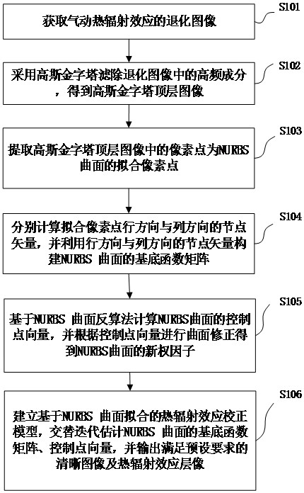
[0049] An embodiment of the present invention provides an aero-optical thermal radiation effect correction method based on NURBS surface fitting, such as figure 1 As shown, the method includes:

[0050] S101: Obtain a degradation image of the aerothermal radiation effect.

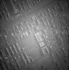
[0051] Among them, the degraded image is a damaged image, and the reasons for the formation of the degraded image of the aerothermal radiation effect include that the high-temperature gas makes the optical window produce serious aero-optical thermal radiation effect noise, which increases the local brightness of the image ...


PUM


Abstract

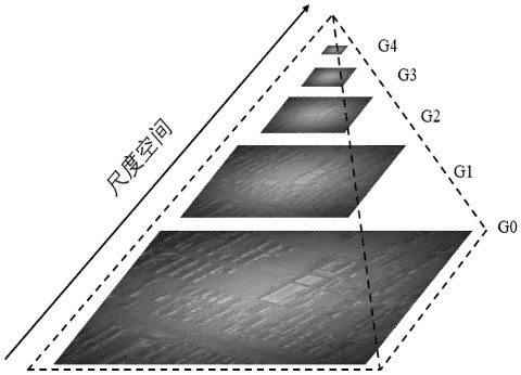
The present invention relates to a method and device for correcting aero-optical thermal radiation effect based on NURBS surface fitting, which comprises: obtaining a degraded image of aerodynamic thermal radiation effect; using a Gaussian pyramid to filter out high-frequency components in the degraded image to obtain the top layer of the Gaussian pyramid Image; extract the pixels in the top image of the Gaussian pyramid as the fitting pixels of the NURBS surface; calculate the node vectors of the fitting pixel points in the row direction and column direction respectively, and use the node vectors in the row direction and column direction to construct the base of the NURBS surface Function matrix; calculate the control point vector of the NURBS surface based on the inverse algorithm of the NURBS surface, and perform surface correction according to the control point vector to obtain the new weight factor of the NURBS surface; establish a thermal radiation effect correction model based on NURBS surface fitting, and alternately iteratively estimate the NURBS surface Basis function matrix, control point vector, and output a clear image and thermal radiation effect layer image that meet the preset requirements. The invention can effectively correct the degraded image to obtain a clear image.

Description

technical field [0001] The invention relates to the technical field of aero-optical image processing, in particular to an aero-optic thermal radiation effect correction method and device based on NURBS (Non-Uniform Rational BSplines, non-uniform rational B-splines) surface fitting. Background technique [0002] The 21st century is an era of high-speed development of aircraft. With the breakthrough of the speed of aircraft, when the aircraft flies in the atmosphere at hypersonic speed, the friction and interaction with the air will generate a strong and complex aerodynamic flow field, and make the optical The temperature of the window rises sharply, and the high-temperature gas makes the optical window produce serious aero-optical thermal radiation effect noise, which increases the local brightness of the image background and degrades the imaging quality, causing great troubles to the optical imaging detection window and optical navigation and positioning system of high-speed ...

Claims


Application Information

Patent Timeline
Patent Type & Authority Patents(China)
IPC IPC(8): G06T5/00
CPCG06T2207/20016G06T5/77G06T5/70
Inventor 洪汉玉叶国庆时愈张丽琴杜敦伟赵欣张天序桑农
Owner WUHAN INSTITUTE OF TECHNOLOGY
Learn More