
Eureka
For R&D, Eureka makes reading and utilizing patents & technical documents easy.
Eureka AIR
Designed for self-driven R&D workflows. Generate viable solutions, solve complex R&D challenges, empower your innovation with AI.

Eureka Materials
Designed for material experts only. Revolutionize your material R&D, from search, analyze, to developing new materials.

TechResearch
Generate reliable direction feasibility study reports for your R&D in just a few steps.

TechSeek
Discover and master advanced knowledge NOW. Basics, ideas, possibilities, all at once.

TechMind
As an expert in R&D Theories, TechMind can generates customized viable solutions instantly.

TechRisk
Analyze your overall solution with one click, know your potential R&D risks in advance.

TechMonitor
Get weekly tech updates, stay abreast of the latest tech innovations and key insights.
Device for automatically replacing resin
An automatic replacement and resin technology, applied in the field of nuclear chemical industry, to achieve the effect of reducing work difficulty, minimizing management, and reducing radiation risks and hazards
- Summary
- Abstract
- Description
- Claims
- Application Information
AI Technical Summary
Problems solved by technology
Method used
Image


Examples
Embodiment 1
[0056] This embodiment provides a device for automatically replacing resin, including:
[0057] The high-level tank is used to hold the resin to be filled, and the high-level tank is connected to the deionized water pipeline;
[0058] The glove box, the high level tank and the controller are set outside the glove box, and the adsorption column, filter and circulation tank are set inside the glove box;
[0059] Adsorption column, the resin inlet of the adsorption column is connected to the liquid outlet of the head tank through the first pipeline;
[0060] A filter, the resin inlet of the filter is connected with the resin outlet of the adsorption column through a second pipeline;
[0061] Circulation tank, the liquid inlet of the circulation tank is connected with the liquid outlet of the filter through the third pipeline, the liquid inlet of the circulation tank is connected with the liquid outlet of the adsorption column through the fourth pipeline, and the liquid outlet of...
Embodiment 2
[0066] Such as Figure 1-5 As shown, the present embodiment provides a device for automatically replacing resin, including:
[0067] The high-level tank 5 is used to hold the resin to be filled, and the high-level tank 5 is connected to the deionized water pipeline;
[0068] The glove box 8, the high level tank 5, and the controller 9 are arranged outside the glove box 8, and the adsorption column 1, the filter 2, and the circulation tank 3 are arranged inside the glove box 8;
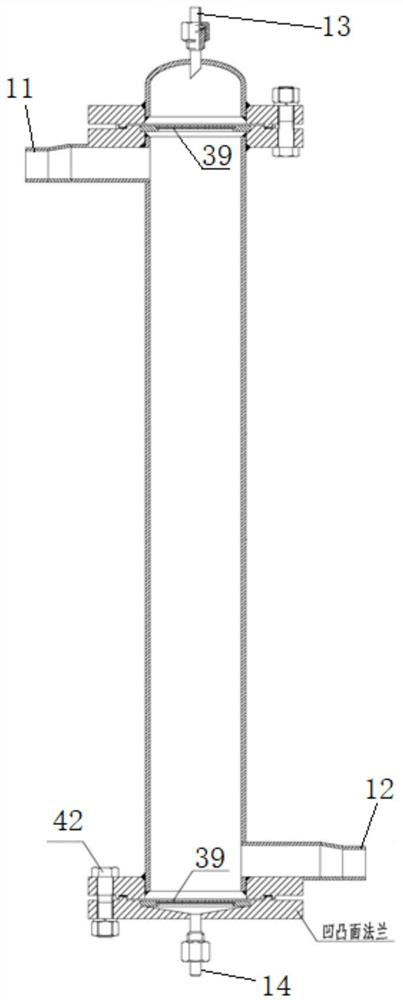
[0069] The adsorption column 1, the resin inlet 11 of the adsorption column is connected with the liquid outlet 53 of the head tank through the first pipeline 18;
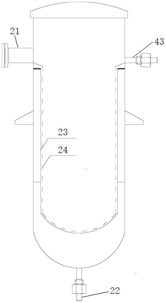
[0070] Filter 2, the resin inlet 21 of the filter is connected with the resin outlet 12 of the adsorption column through the second pipeline 19;
[0071] The circulation tank 3, the liquid inlet 31 of the circulation tank is connected with the liquid outlet 22 of the filter by the third pipeline 25, the liquid inlet 31 of the circulation ...
PUM
 Abstract
Description
Claims
Application Information
 - R&D Engineer
- R&D Manager
- IP Professional
- Industry Leading Data Capabilities
- Powerful AI technology
- Patent DNA Extraction
Browse by: Latest US Patents, China's latest patents, Technical Efficacy Thesaurus, Application Domain, Technology Topic, Popular Technical Reports.
© 2024 PatSnap. All rights reserved.Legal|Privacy policy|Modern Slavery Act Transparency Statement|Sitemap|About US| Contact US: help@patsnap.com