Compact jet dispensing valve with adjustable glue discharge amount and glue spraying method of compact jet dispensing valve

A compact, high-volume glue technology, applied to the surface coating liquid device, coating, etc., can solve the problems of difficult adjustment of glue output, small glue injection, limited material deformation, etc., to ensure the working life and motion stability, improve work efficiency, and reduce manufacturing costs

Active Publication Date: 2022-02-11
上海盛普流体设备股份有限公司 +1
View PDF8 Cites 2 Cited by
  • Summary
  • Abstract
  • Description
  • Claims
  • Application Information

AI Technical Summary

Problems solved by technology

Compared with pneumatic drive, piezoelectric material can provide higher driving frequency and achieve higher precision glue volume control, but the cost of piezoelectric stack material is high, the driving displacement is small (micro displacement), the glue injection volume is small and the delivery Difficult to adjust after
[0004] For example, the patent publication number CN 105289934 A discloses a diamond-shaped amplification mechanism, and the patent publication number CN209189133 U discloses a triangular amplification mechanism. Small problem, but there are several disadvantages: 1. The amplification mechanism and its auxiliary parts take up too much space; 2. The deformation of the material is limited. In order to achieve the expected striker stroke, more piezoelectric ceramic actuator consumables are needed. Resulting in higher costs; 3. It is difficult to adjust the amount of glue output (stroke of the firing pin);

Method used


Image

  • Compact jet dispensing valve with adjustable glue discharge amount and glue spraying method of compact jet dispensing valve
  • Compact jet dispensing valve with adjustable glue discharge amount and glue spraying method of compact jet dispensing valve
  • Compact jet dispensing valve with adjustable glue discharge amount and glue spraying method of compact jet dispensing valve

Examples


Embodiment Construction

[0028] In order to make the object, technical solution and advantages of the present invention clearer, the present invention will be further described in detail below in conjunction with the accompanying drawings and embodiments.

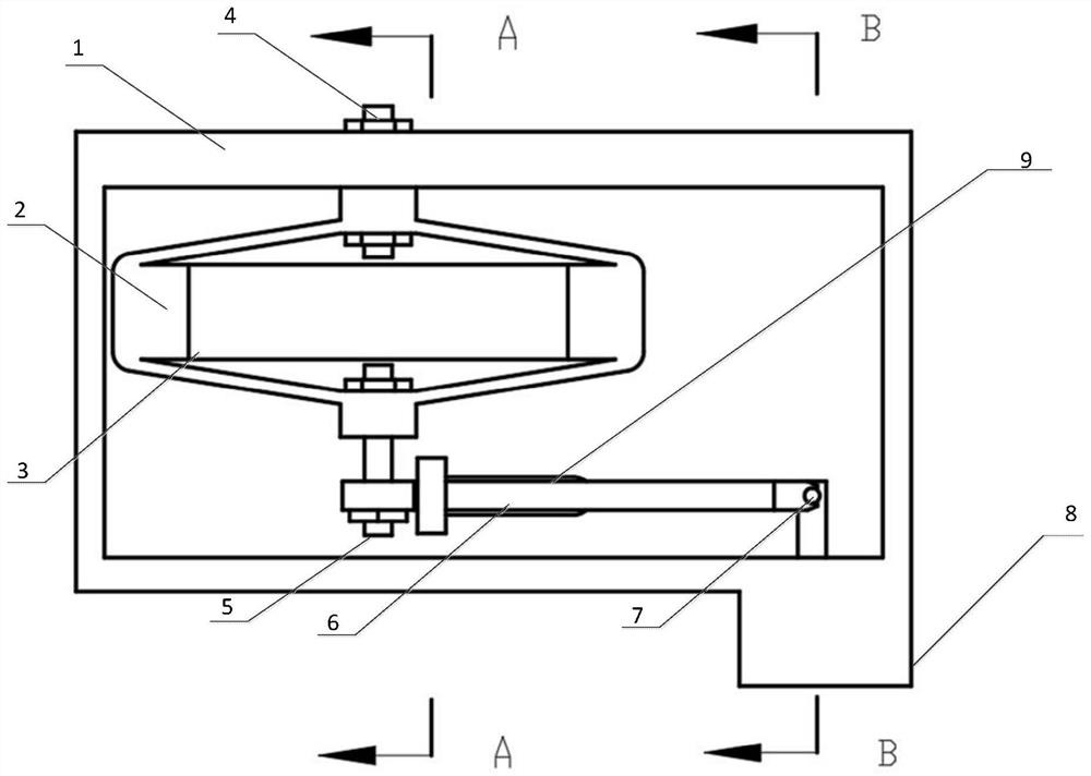
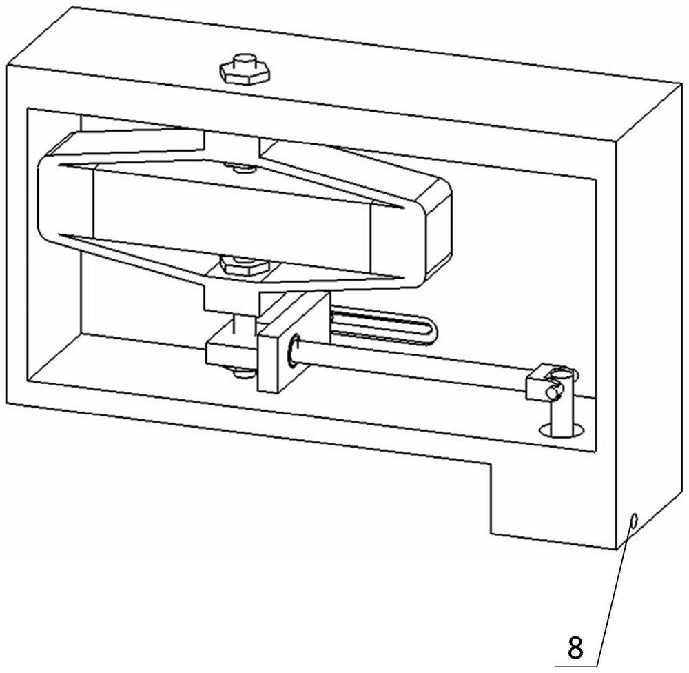
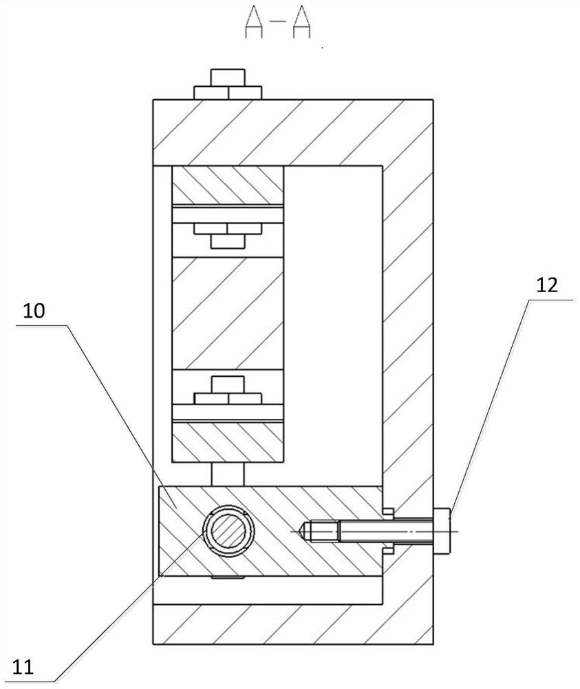
[0029] Such as figure 1 , 2 As shown in and 3, a compact jet dispensing valve with adjustable glue output includes a dispensing valve housing 1, a primary displacement amplifying mechanism, a secondary displacement amplifying mechanism and a striker assembly; the primary displacement amplifying mechanism includes a piezoelectric The ceramic actuator 3 and the hollow flexible ring 2; the piezoelectric ceramic actuator 3 is arranged horizontally, and the two ends are respectively fixed to the two inner walls of the hollow flexible ring 2; the top of the hollow flexible ring 2 is fixed to the dispensing valve housing 1 The secondary displacement amplification mechanism includes a connecting lever 6, a bearing frame with arms 10 and a spherical ball b...


PUM


Abstract

The invention discloses a compact jet dispensing valve with an adjustable glue output amount and a glue spraying method of the compact jet dispensing valve. An existing jet dispensing valve is small in driving displacement in a piezoelectric driving mode. A piezoelectric ceramic actuator is horizontally arranged and is fixed to the inner side wall of a hollow flexible ring; the top end of the hollow flexible ring is fixed to a dispensing valve shell, and the bottom end is fixed to one end of a connecting lever; the middle part of the connecting lever is supported on a bearing frame with an arm through an insert ball bearing; the bearing frame with the arm is fixed to the dispensing valve shell; the top end of a firing pin is hinged to the other end of the connecting lever through a hinge, and the bottom end of the firing pin is embedded into a firing pin cavity formed in the dispensing valve shell; a sealing gasket is arranged between the side surface of the firing pin and the firing pin cavity; the firing pin cavity is divided into two cavities by the firing pin and the sealing gasket, and the cavity close to the bottom of the firing pin cavity is a rubber cavity; a glue solution channel is formed in the side wall of the glue cavity; and a glue outlet communicated with the glue cavity is formed in the bottom of the firing pin cavity. By means of the two-stage amplification effect of the hollow flexible ring and the connecting lever, the displacement of the firing pin is large, and the glue output amount is large.

Description

technical field [0001] The invention relates to the technical field of glue dispensing, in particular to a compact jet glue dispensing valve with adjustable glue output and a glue spraying method thereof. Background technique [0002] Fluid dispensing technology belongs to precision instrument technology, widely used in optics, optoelectronics, semiconductor manufacturing and packaging, medicine and other industries. The dispensing forms mainly include contact type and spray type. Among them, jet dispensing benefits from its higher dispensing frequency and smaller glue volume, and its application is more common. When working, the jet dispensing valve is not in contact with the target, and the glue near the glue outlet is extruded through the high-frequency reciprocating motion of the striker inside the valve body, and the glue spray trajectory such as points and lines is constructed to achieve coating at the target position. [0003] At present, there are mainly two driving...

Claims


Application Information

Patent Timeline
Patent Type & Authority Applications(China)
IPC IPC(8): B05C5/02
CPCB05C5/0225
Inventor 刘燕付建义李天智武传宇
Owner 上海盛普流体设备股份有限公司
Why Eureka
Try Eureka