Urinary surgery medical waste crushing and recycling device
A medical waste and recovery device technology, applied in the direction of solid waste removal, waste disinfection or sterilization methods, transportation and packaging, etc., can solve the problems of unfavorable recycling, large volume, easy to produce bacterial growth, etc., and achieve convenient recycling Handling and avoiding the effect of inadvertent pop-up
- Summary
- Abstract
- Description
- Claims
- Application Information
AI Technical Summary
Problems solved by technology
Method used
Image
Examples
Embodiment 1
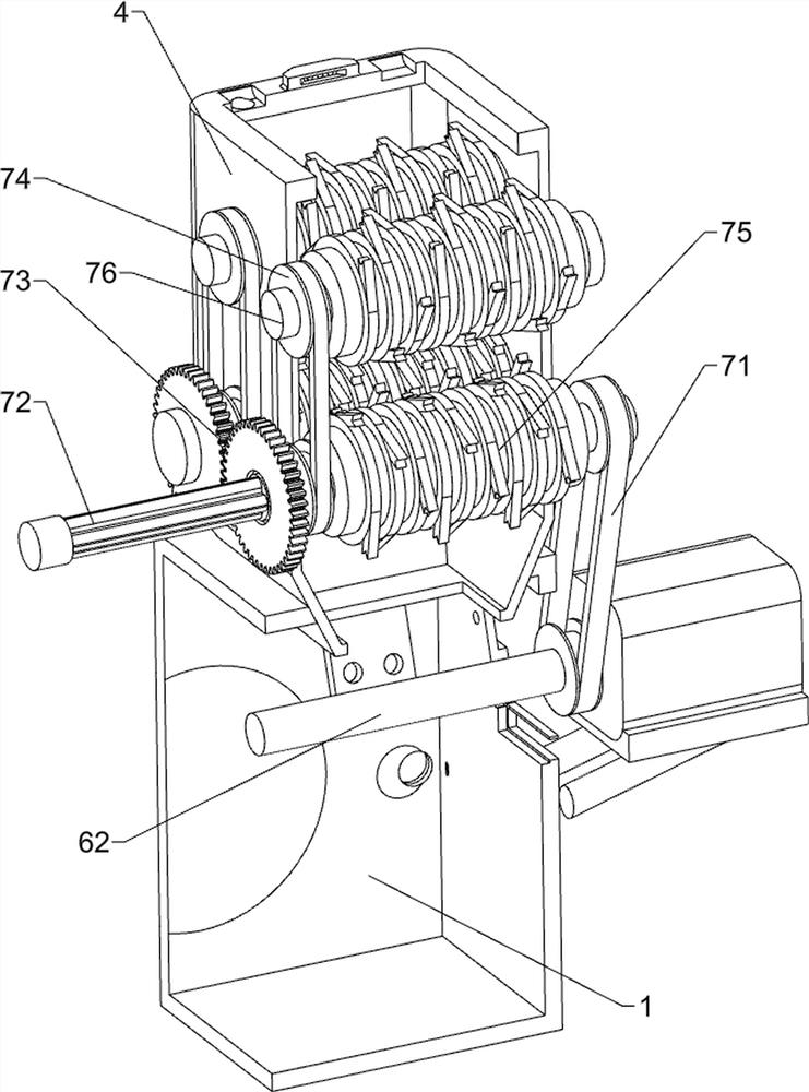
[0035] A device for crushing and recycling medical waste in urology, such as Figure 1-Figure 3As shown, it includes a machine bin body 1, a buffer base 2, a sealing cover plate 3, a lower barrel 4, a start button 51, a stop button 52, a feeding mechanism 6 and a crushing mechanism 7, and the outer bottom of the machine bin body 1 is provided with a buffer The base 2, the right side of the outer top of the machine compartment 1 is fixedly connected with a sealing cover 3, the lower left side of the outer top of the machine compartment 1 is provided with a lower material tube 4 and communicated with it, and the middle part of the outer right side of the machine compartment 1 is provided with a start button 51 , The middle part of the outer right side of the machine bin body 1 is provided with a stop button 52, the machine bin body 1 is provided with a feeding mechanism 6, and a crushing mechanism 7 is arranged between the feeding mechanism 6 and the lower barrel 4.
[0036] The...
Embodiment 2
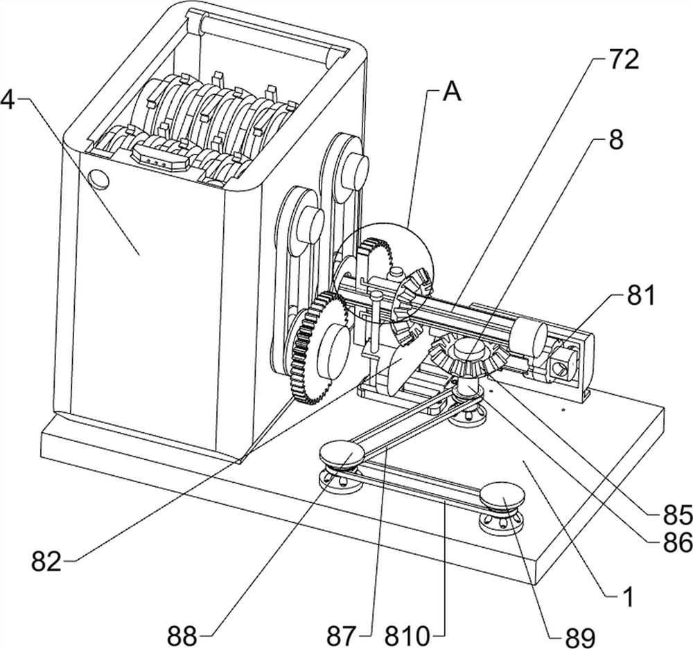
[0040] On the basis of Example 1, such as Figure 4-Figure 11 As shown, a lifting mechanism 8 is also included, and the lifting mechanism 8 includes an electric push rod 81, a positioning slider 82, a sliding positioning block 83, a sliding bevel gear 84, a reversing bevel gear 85, a positioning stub 86, the third transmission assembly 87. Ascending screw 88, descending screw 89, fourth transmission assembly 810, positioning guide column 811, limit short column 812, contact switch 813, material receiving buffer hopper 814, first pressure sensor 815, lower hopper 816, telescopic Limiting block 817, hinged lifting platform 818, positioning spring 819, movable slide block 820, buffer push rod 821, travel switch 822 and feeding box 823, the rear part of the right side of the outer top of the machine warehouse body 1 is fixedly connected with an electric push rod 81 , the outer top of the machine compartment body 1 is provided with a sliding positioning slider 82 in the middle of t...
Embodiment 3
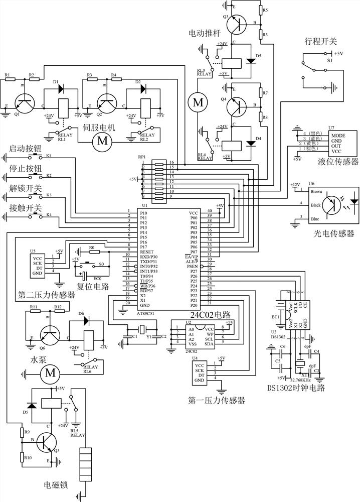
[0045] On the basis of embodiment 1 and embodiment 2, such as Figure 12 with Figure 13 As shown, a positioning mechanism 10 is also included, and the positioning mechanism 10 includes a spring shading plate 101, a first positioning guide rail 102, a second positioning guide rail 103 and a photoelectric sensor 104. There is a spring visor 101, a first positioning guide rail 102 is provided on the left side of the bottom of the machine compartment body 1, a second positioning guide rail 103 is provided on the left side of the bottom of the machine compartment body 1, and both front and rear sides are provided on the left side of the machine compartment body 1. There is a photosensor 104 .
[0046] Also comprises locking mechanism 11, and locking mechanism 11 comprises material blocking plate 111, second pressure sensor 112, unlocking switch 113 and electromagnetic lock 114, and the material blocking plate 111 is hingedly arranged on the upper side of unloading barrel 4 rear p...
PUM
 Abstract
Description
Claims
Application Information
 - R&D
- Intellectual Property
- Life Sciences
- Materials
- Tech Scout
- Unparalleled Data Quality
- Higher Quality Content
- 60% Fewer Hallucinations
Browse by: Latest US Patents, China's latest patents, Technical Efficacy Thesaurus, Application Domain, Technology Topic, Popular Technical Reports.
© 2025 PatSnap. All rights reserved.Legal|Privacy policy|Modern Slavery Act Transparency Statement|Sitemap|About US| Contact US: help@patsnap.com


