
Construction method for embedded part of transformer substation

A construction method and a technology of embedded parts, which are applied to building components, floors, buildings, etc., can solve the problems that the embedded parts cannot be guaranteed not to deviate, affect the position and height of the embedded parts, and the position deviation of the embedded parts, etc., to achieve Reduce rework and repair work, improve quality, and avoid the effect of displacement of steel bars

Pending Publication Date: 2022-02-11
郑州祥和集团有限公司 +2
View PDF26 Cites 0 Cited by
  • Summary
  • Abstract
  • Description
  • Claims
  • Application Information

AI Technical Summary

Problems solved by technology

[0002] With the implementation of the standardization of substation civil engineering technology, the qualified and excellent embedded parts have become more and more important. The main function of the embedded parts is a more convenient process for later installation. The traditional construction technology of embedded parts is to directly bind the embedded parts to the main reinforcement of beams, slabs and other components, but this The construction process has the following disadvantages: during concrete construction, there are various processes on the working surface to be constructed at the same time, and the movement of vehicles and personnel will cause the displacement of the steel bars, which will affect the position and height of the embedded parts welded on it, resulting in the failure of the embedded parts. If there is a deviation in the position, even if a lot of manpower and material resources are spent on rectification in the later period, it cannot guarantee that the embedded parts will not deviate; when the concrete is poured, the impact force of the concrete and the vibrating rod will inevitably touch the steel bar, resulting in the displacement of the steel bar. There is a large displacement of the embedded parts; because the embedded parts cannot meet the expected requirements, it is necessary to correct the embedded parts when welding the cable bracket or channel steel in the later stage, which increases the amount of work and delays the construction period

Method used


Image

  • Construction method for embedded part of transformer substation

Examples


Embodiment

[0024] Example: Embedded parts can be divided into stressed embedded parts and structural embedded parts, which are usually composed of two parts: one is embedded in concrete, and this kind of anchor bar generally adopts grade I or II steel bars; The anchor plate on the surface of the concrete is generally made of No. 3 steel plate or angle steel. The main function of the embedded parts is a more convenient process for later installation. It is very firm to directly weld the bracket or channel steel to the embedded parts during installation. Without embedded parts, the installation bracket or channel steel must be drilled in the floor, etc., and the expansion screws are installed. .

[0025] In the substation civil engineering, a large number of cable supports and channel steel between equipment need to be installed. The cable support and channel steel are all welded on the 10cm*10cm embedded parts that are pre-embedded in the concrete.

[0026] The following is a specific me...


PUM


Abstract

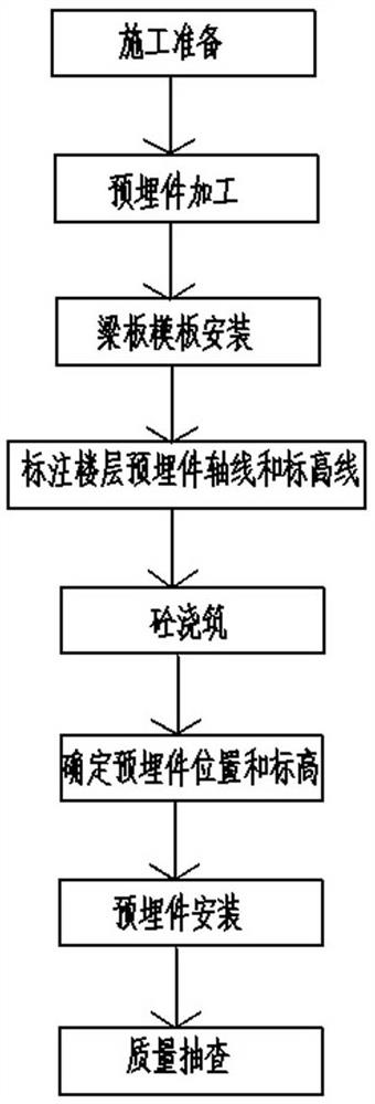
The invention discloses a construction method for an embedded part of a transformer substation. The construction method comprises the following steps of (1) construction preparation; (2) processing an embedded part; (3) beam plate formwork installation; (4) the axis and the elevation line of the floor embedded part being marked; (5) pouring concrete; (6) determining the position and elevation of the embedded part; (7) mounting an embedded part; and (8) carrying out quality spot check; II-level steel bars with the length of 10 cm and thickness of 12 cm are selected as anchoring steel bars on the embedded part; for the installation of the embedded part, a practical field is arranged on a construction site before construction, and constructors are organized to carry out practical operation practice on the situation that the anchor tie bar and the concrete of the embedded part are not compactly combined; and after a worker finishes the concrete surface layer finishing process, the embedded part process is also finished at the same time. The method can effectively solve a problem that the embedded part anchor tie bar and the concrete are not compactly combined.

Description

Technical field: [0001] The invention relates to a construction method of embedded parts, in particular to a construction method of embedded parts in substations. Background technique: [0002] With the implementation of the standardization of substation civil engineering technology, the qualified and excellent embedded parts have become more and more important. The main function of the embedded parts is a more convenient process for later installation. The traditional construction technology of embedded parts is to directly bind the embedded parts to the main reinforcement of beams, slabs and other components, but this The construction process has the following disadvantages: during concrete construction, there are various processes on the working surface to be constructed at the same time, and the movement of vehicles and personnel will cause the displacement of the steel bars, which will affect the position and height of the embedded parts welded on it, resulting in the f...

Claims


Application Information

Patent Timeline
Patent Type & Authority Applications(China)
IPC IPC(8): E04B5/32E04B1/41E04G21/18
CPCE04B5/32E04B1/41E04G21/185
Inventor 吕明辉王丽萍刘汉超谢亚飞李鑫张恒彭家颖陈德龙
Owner 郑州祥和集团有限公司
Learn More