Design method for reasonable bridge forming state of self-anchored suspension bridge

A technology for self-anchored suspension bridges and completed bridges, applied in suspension bridges, design optimization/simulation, bridges, etc., can solve problems such as low computational efficiency, and achieve the effect of improving computational efficiency

Pending Publication Date: 2022-02-11
SHANGHAI MUNICIPAL ENG DESIGN INST GRP
View PDF0 Cites 2 Cited by
  • Summary
  • Abstract
  • Description
  • Claims
  • Application Information

AI Technical Summary

Problems solved by technology

[0003] The technical problem to be solved by the present invention is to provide a design method for a self-anchored suspension bridge in a reasonable bridge state in order to overcome th

Method used


Image

  • Design method for reasonable bridge forming state of self-anchored suspension bridge
  • Design method for reasonable bridge forming state of self-anchored suspension bridge
  • Design method for reasonable bridge forming state of self-anchored suspension bridge

Examples


Embodiment 1

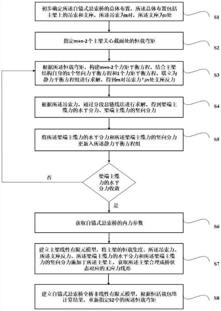
[0051] An embodiment of the present invention provides a method for designing a reasonable bridge state of a self-anchored suspension bridge, the method comprising the following steps:

[0052] S1. Preliminarily determine the overall layout of the self-anchored suspension bridge. The overall layout includes the slings and supports on the main girder, m pairs of slings, and n places of supports;

[0053] S2. Specify the dead-load bending moment at the concerned section of m+n-2 main beams;

[0054] S3. According to the constant load bending moment, m+n-2 moment balance equations are constructed, combined with one vertical force balance equation and one moment balance equation of the main beam structure itself, and simultaneously solve the static force balance equation group, Obtain m pairs of sling force and support reaction force at n;

[0055] Specifically, the solution process is as follows: set the moment balance equation as ∑M k (R i )+∑M k (G k )+H(y k -y H )+V(x ...

Embodiment 2

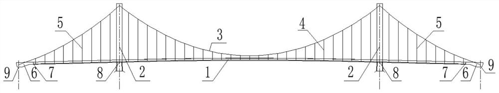
[0097] The present invention will be described in detail below in conjunction with the Jiasong Huangpu River Bridge as an example. The concrete span arrangement of the bridge is: 130+336+130=396m.

[0098] Such as figure 1 As shown, the main girder is composed of a steel girder 1, a steel-concrete joint section 7 of the main girder, and a concrete anchorage section 6. The main girder and the main tower 2 form a stress relationship through the main cable 3, the mid-span sling 4 and the side-span sling 5. Each side of the side-span sling is composed of 9 pairs of slings, and the direction from the side support 9 to the middle support 8 is L(R)S9~L(R)S1 respectively; the middle-span sling 4 is composed of 27 pairs of slings , LM13~LM1, M0, RM1~RM13 from left to right in the numbering diagram; there are 4 support points for the main girder of the whole bridge, which are 2 side supports 9 and 2 middle supports 8 respectively.

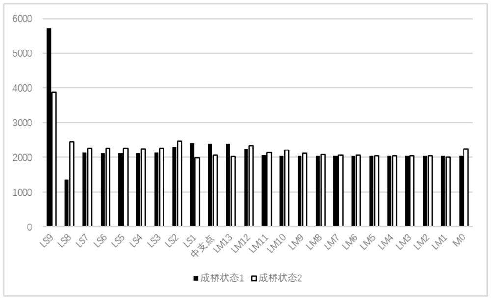
[0099] Such as figure 2 as shown, figure 2 Listed...


PUM


Abstract

The invention provides a design method for the reasonable bridge forming state of a self-anchored suspension bridge. The design method comprises the following steps S1, determining the overall arrangement of the self-anchored suspension bridge preliminarily; s2, appointing dead load bending moments at the concerned sections of m + n-2 main beams; s3, according to the dead load bending moment, building m + n-2 moment balance equations, and obtaining m pairs of sling force and n support reaction force by combining one vertical force balance equation and one moment balance equation of the main beam structure; s4, according to the sling force, performing solving through a segmented catenary method, and obtaining the horizontal component force and the vertical component force of the beam end main cable force; s5, updating the horizontal component force and the vertical component force of the beam end main cable force into the static equilibrium equation set; and S6, circulating the steps S3, S4 and S5 until the horizontal component force converges, and obtaining the internal force parameters of the self-anchored suspension bridge. By specifying the concerned section bending moment and depending on the static balance condition, the structure parameters needing to be determined are reduced in the reasonable finished bridge state determination process, and the calculation efficiency is improved.

Description

technical field [0001] The invention relates to the technical field of bridge structure design, in particular to a design method for a self-anchored suspension bridge in a reasonable bridge state. Background technique [0002] The self-anchored suspension bridge is a high-order statically indeterminate system (towers, beams, and cables) with significant structural geometric nonlinear effects. Due to the large number of suspension cables and the mutual coupling of the main girder and main cable, it is difficult to determine a reasonable bridge state. The rigidly supported continuous beam method widely used at present depends on the deformation coordination conditions in the process of calculating the suspension force of the main beam and the reaction force of the support. Therefore, a large number of structural parameters need to be determined, which will lead to low calculation efficiency. Contents of the invention [0003] The technical problem to be solved by the present...

Claims


Application Information

Patent Timeline
IPC IPC(8): G06F30/23G06F30/13E01D11/02
CPCG06F30/23G06F30/13E01D11/02G06F2119/14
Inventor 许骏李福鼎孙东超戴建国顾超陈逸群
Owner SHANGHAI MUNICIPAL ENG DESIGN INST GRP
Why Eureka
Try Eureka