Millimeter wave anti-blocking multi-unmanned aerial vehicle deployment method based on building geometric analysis

A geometric analysis, multi-UAV technology, applied in baseband system components, wireless communications, radio transmission systems, etc., can solve the problem of greed, millimeter wave signal line-of-sight and non-line-of-sight transmission path loss is very different, not given. UAV location deployment plan and other issues, to achieve the effect of small path loss and large path loss

Pending Publication Date: 2022-02-11
NORTHWEST UNIV
View PDF0 Cites 1 Cited by
  • Summary
  • Abstract
  • Description
  • Claims
  • Application Information

AI Technical Summary

Problems solved by technology

[0004] To sum up, the existing UAV deployment methods have their own advantages and disadvantages: the UAV deployment method based on the K-means algorithm proposes user clustering and UAV deployment methods, but fails to take into account the millimeter wave signal The characteristics of being easily blocked by obstacles cannot be well adapted to the millimeter wave communication environment; the effective deployment of a multi-UAV communication system based on the geometric analysis of buildings takes into account the characteristics of the large difference in line-of-sight and non-line-of-sight transmission path losses of millimeter-wave signals, A greedy user scheduling algorithm is proposed, but no UAV position deployment scheme is given

Method used


Image

  • Millimeter wave anti-blocking multi-unmanned aerial vehicle deployment method based on building geometric analysis
  • Millimeter wave anti-blocking multi-unmanned aerial vehicle deployment method based on building geometric analysis
  • Millimeter wave anti-blocking multi-unmanned aerial vehicle deployment method based on building geometric analysis

Examples


Embodiment Construction

[0055] The specific content of the present invention will be further described below in conjunction with the specific embodiments:

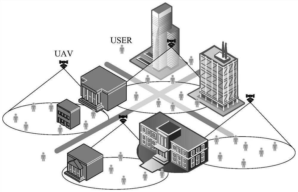
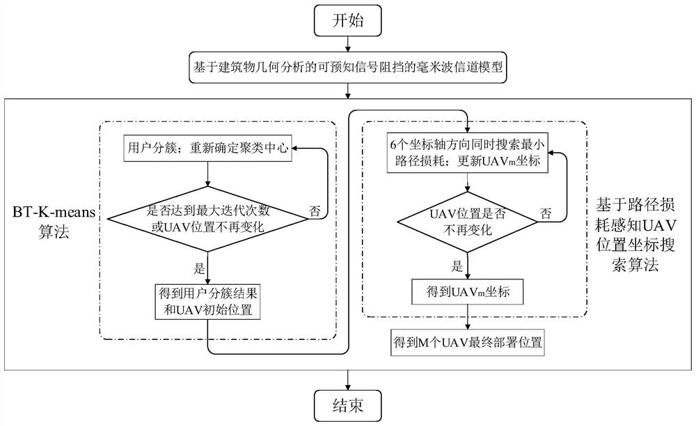
[0056] For figure 1 The urban environmental communication system, which is disclosed in the present invention, a millimeter wave anti-blocking multi-drone deployment method based on building geometric analysis, see figure 2 The following steps are specifically included.

[0057] Step 1. Set a MR frame drone, the urban environmental communication system of K users, the position of the kth user is δ k = (X k Y k ,z k ), X k Y k ,z k The X, Y, Z axial coordinate of the kth user, respectively; the position of the March drone is ξ m = (X m Y m ,z m ), X m Y m ,z m The X, Y, Z axis coordinate of the March Machine; urban building height information is a matrix H; the user is randomly distributed around the building, each drone can serve multiple users at the same time. Millimeter waves are communicated with millimeters between drones and users. Suppose the ...


PUM


Abstract

The invention discloses a millimeter wave anti-blocking multi-unmanned aerial vehicle (UAV) deployment method based on building geometric analysis, and mainly solves the problems of user clustering and UAV deployment when UAVs provide communication services for users in an urban environment. The specific method comprises the following steps: firstly, establishing a millimeter wave channel model capable of predicting signal blocking based on building geometric analysis; providing a BT-K-means multi-unmanned aerial vehicle clustering algorithm, and performing multiple iterations according to a minimum path loss principle to obtain a clustering result of the user and an initial position of the unmanned aerial vehicle; in each cluster, providing an unmanned aerial vehicle position coordinate searching method based on path loss sudden change perception, searching the minimum path loss value in six coordinate axis directions at the same time, unmanned aerial vehicle coordinates are continuously updated through multiple iterations, unmanned aerial vehicle position optimization is achieved, and the final deployment position of each unmanned aerial vehicle is obtained. According to the algorithm provided by the invention, the number of sight distance transmission users can be increased, and meanwhile, the total path loss of the whole system is effectively reduced.

Description

Technical field [0001] The present invention belongs to the field of millimeter wave drone wireless communication network, involving clustering methods and optimization problems, especially for urban environment wireless communication networks that provide communication services from multiple drones to multiple users, establish a building The geometric analysis of the presenced signal blocking millimeter wave channel model, proposes a two-stage deployment algorithm based on block detection of K-Means multi-drone clustering and path loss mutation-perceived drone position coordinate search, so that The number of transmitted users is increased while effectively reducing the total path loss of the wireless communication system. Background technique [0002] In the course of the Wireless Communication System for communication deployment of UAV, UNMANED AERIAL VEHICLE, Hua Qu, Wenna Zhang, Jihong Zhao and Zhirong Luan published "Rapid Deployment Ofuavs Based on Bandwidth Resources in E...

Claims


Application Information

Patent Timeline
IPC IPC(8): H04B7/185H04B17/382H04L25/02H04W16/18
CPCH04B7/18506H04B17/382H04L25/024H04W16/18
Inventor 李小亚李凡周伟王浩琳屈锁杨泽磊贺晨彭进业
Owner NORTHWEST UNIV
Why Eureka
Try Eureka