A Broadband High Power Low Loss Ring Power Distribution Combiner

A high-power, low-loss technology, applied in waveguide-type devices, electrical components, connecting devices, etc., can solve the problem of increased power distribution/combination path loss, reduced power distribution and combination efficiency, and difficulty in effectively improving heat dissipation efficiency, etc. problems, to achieve good heat dissipation efficiency, improved conduction efficiency, and low path loss.

Active Publication Date: 2016-05-25
CHINA ELECTRONIS TECH INSTR CO LTD
View PDF3 Cites 0 Cited by
  • Summary
  • Abstract
  • Description
  • Claims
  • Application Information

AI Technical Summary

Problems solved by technology

In order to increase the operating frequency bandwidth and the isolation between the two output ports 10 and 11, it must be solved by increasing the number of isolation resistors, but since the power distribution loop and the isolation loop overlap in this structure, when the power When the number of points and isolation loops increases, the loss of the power distribution / combination path will increase, resulting in a rapid decline in the efficiency of power distribution / combination
[0005] Existing planar circuit power distribution / combination technology, taking Wilkinson power distribution / combiner as an example, although it adopts a multi-section structure to obtain a wider operating frequency band and higher isolation, its disadvantages increase with the number of nodes. The insertion loss increases rapidly, which greatly reduces the efficiency of power distribution and synthesis; in addition, because the power distribution loop and the isolation loop overlap in this structure, the isolation resistance inside the loop is limited by the size of the overall structure, so it cannot be done To increase the heat dissipation area, therefore, the power capacity is greatly limited
If one of the amplifiers is damaged, or the ports of any one of the two branches are not well matched, the power of the electromagnetic wave reflected by the port to both ends of the isolation resistance will increase accordingly, so it is difficult to ensure that the isolation resistance is affected by the high power. Although it is possible to increase the power capacity by replacing the thin-film resistors on the microstrip circuit with thick-film resistors, it is difficult to effectively improve the heat dissipation efficiency while increasing the cost. Greatly reduced reliability when working or port mismatch

Method used


Image

  • A Broadband High Power Low Loss Ring Power Distribution Combiner
  • A Broadband High Power Low Loss Ring Power Distribution Combiner
  • A Broadband High Power Low Loss Ring Power Distribution Combiner

Examples


Embodiment 1

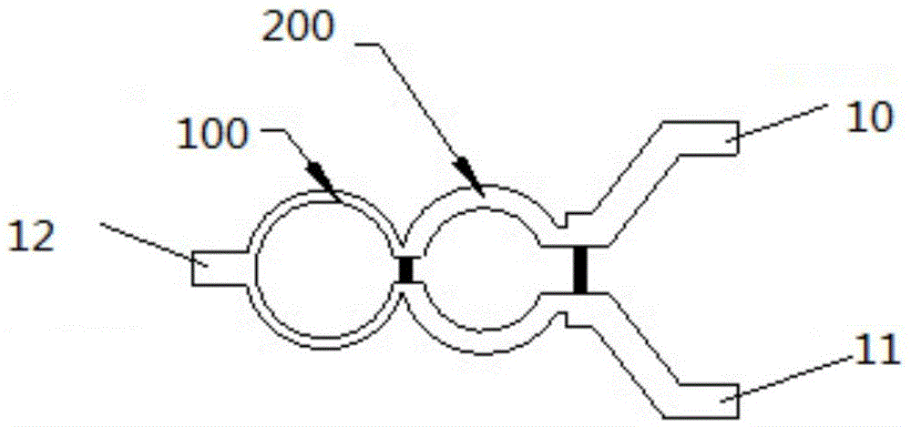
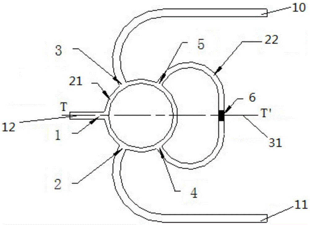
[0027] The structural diagram of the ring power distribution / combination technology adopted in the present invention is as follows figure 2 shown. The structure cleverly combines the working principle of the microstrip ring bridge, and its whole is mainly composed of a power distribution ring and one or more isolation rings. It improves the four-way branch structure on the microstrip ring in the traditional microstrip ring bridge to a five-way branch structure, that is, a node 5 is added between node 3 and node 4 . So that the path difference between node 5 and node 3 is a quarter wavelength λg / 4, and the path difference between node 5 and node 4 is half wavelength λg / 2. The impedance of the power distribution ring is 50Ω impedance times, the radius of the ring is about a quarter wavelength λg / 4 of the central frequency. When the electromagnetic wave is input from the input port 12, since the phase of the electromagnetic wave arriving at node 2 and node 3 is the same and ...

Embodiment 2

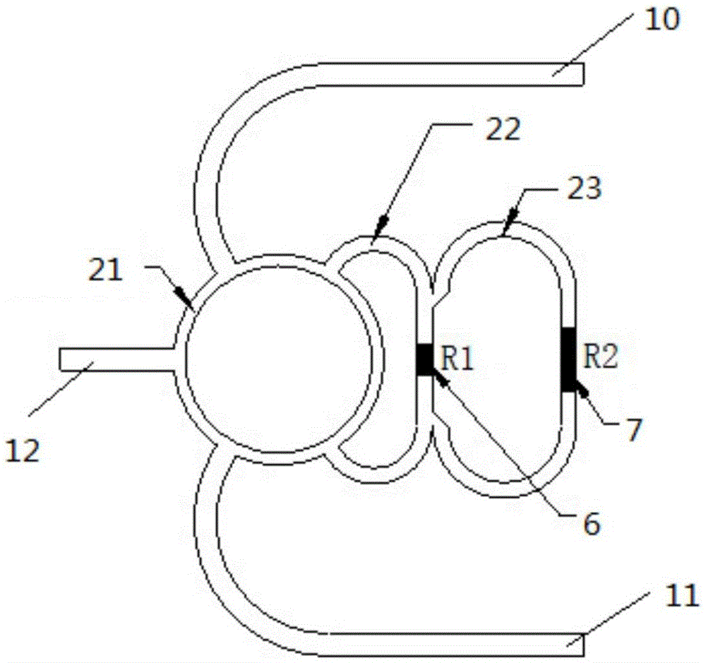
[0029] On the basis of the above examples, if image 3 As shown, the present invention also provides that the whole is mainly composed of a power distribution ring 21 and two isolation rings 22 and 23 . The two paths connected by the power distribution ring 21 are used as two output paths of the power distribution / combiner, and the ports thereof are respectively called the output port 10 and the output port 11 . A thin-film resistor 6 is connected in series on the isolation ring 22, and a thin-film resistor 7 is connected in series on the isolation ring 23. The signal loaded on both ends of the isolation resistor is very small, so the power consumption carried by the isolation resistor is very small, thereby improving the power capacity of the structure. and reliability. At the same time, since the area of ​​the isolation resistor can be adjusted more conveniently, the isolation resistor does not need to be made into a thick film resistor, thereby reducing the production cost...

Embodiment 3

[0031] On the basis of the above embodiments, it is further described that a broadband high-power low-loss ring power distribution combiner includes a power distribution ring and at least one isolation ring, and the isolation ring is located outside the power distribution ring.

[0032] In the broadband high-power low-loss ring power distribution combiner, there is one isolation ring.

[0033] The broadband high-power low-loss ring power distribution synthesizer, wherein, one input port and two output ports are set on the power distribution ring; the two output ports communicate with the power through the second node and the third node The distribution ring is connected; the isolation ring is connected to the power distribution ring through the fourth node and the fifth node; the second node and the fourth node are located on one side, and the third node and the The fifth node is on the other side. The second node and the third node have the same phase and amplitude; the four...


PUM


Abstract

The invention provides a broadband high-power low-loss circular power allocation synthesizer which comprises a power allocation ring and at least one isolating ring, wherein the isolating ring is located on the outer portion of the power allocation ring. According to the technical scheme, the broadband high-power low-loss circular power allocation synthesizer is characterized in that low loss and broadband are achieved, and high amplitude and phase consistency exists between two branch circuits. The working principle of a micro-strip annular bridge is used, and therefore the problems of isolation resistance power capacity and insertion loss increase in a traditional Wilkinson power allocation synthesizer can be solved effectively.

Description

technical field [0001] The invention belongs to the technical field of ring power distribution combiner, and in particular relates to a ring power distribution combiner with wide band, high power and low loss. Background technique [0002] The broadband high-efficiency power synthesis technology of microwave signals is an important part of many fields such as high-power test systems, microwave and millimeter wave communication systems, and electromagnetic compatibility testing. Key technologies that need to be addressed. [0003] A planar power combiner is a microwave and millimeter wave circuit that combines multiple input signal energies into one output signal energy, and can also in turn divide one signal energy into multiple output channels. At this time, it can also be called a power divider. Traditional microwave and millimeter-wave planar power distribution and synthesis circuits are generally implemented with Lange couplers or Wilkinson power dividers plus quarter-w...

Claims


Application Information

Patent Timeline
Patent Type & Authority Patents(China)
IPC IPC(8): H01P5/12H01P5/16
Inventor 孙国泉姜万顺宁曰民
Owner CHINA ELECTRONIS TECH INSTR CO LTD
Why Eureka
Try Eureka