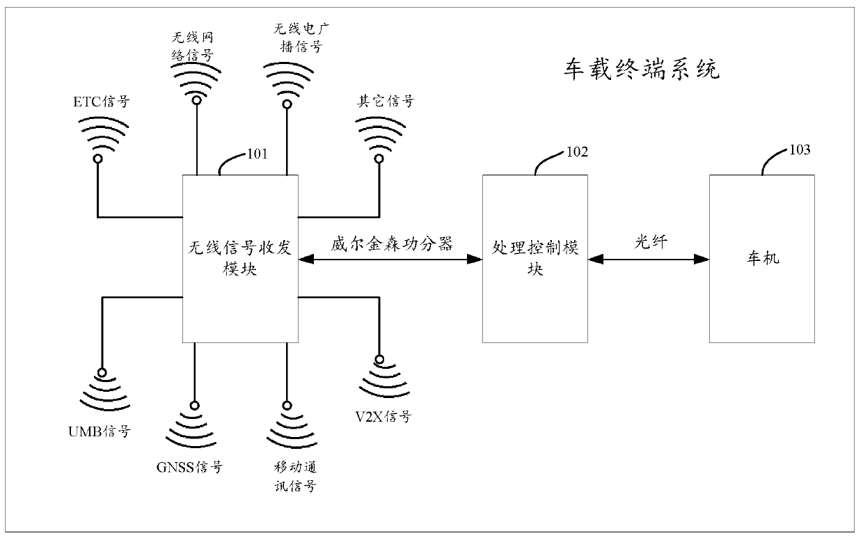
Vehicle-mounted terminal system
A vehicle-mounted terminal and antenna technology, applied in the field of vehicles, can solve the problems of high development cost, high development difficulty, difficult cycle control, etc., and achieve the effect of reducing development cost and avoiding development difficulty
- Summary
- Abstract
- Description
- Claims
- Application Information
AI Technical Summary
Problems solved by technology
Method used
Image
Examples
specific Embodiment approach 1
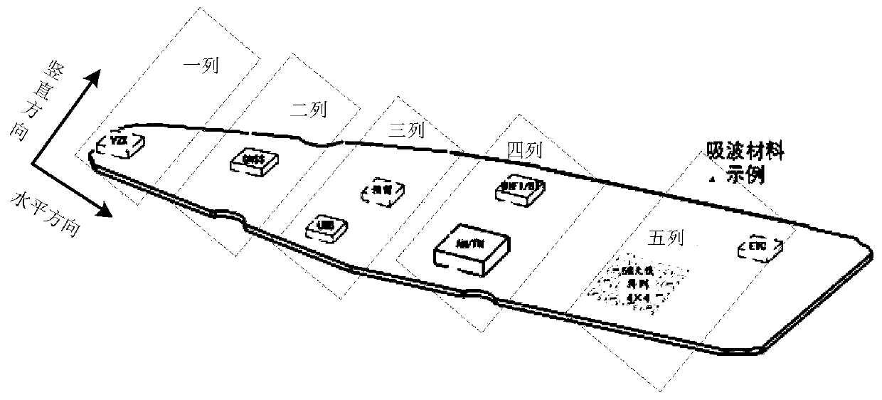
[0049] In practical applications, considering that the problem of signal mutual interference between antennas with similar signal frequency bands is more prominent, in the embodiment of this specification, spaced deployment can be used between antennas with similar signal frequency bands. Specifically, it can include: using Antennas with similar signal frequency bands on the circuit board are deployed in such a manner that the distance between antennas with similar signal frequency bands on the circuit board is not less than a preset distance threshold. Wherein, the preset distance threshold may be determined based on an experimentally obtained correspondence between the degree of mutual interference between signals and the distance between antennas. For example, assuming that the tolerable degree of mutual interference between signals is generated when the distance between antennas is not less than d, then d may be used as the distance threshold.
[0050] It can be understood...
specific Embodiment approach 2
[0059] In practical applications, although the distance between antennas with similar signal frequency bands in the above method 1 is not less than the preset distance threshold, the problem of signal mutual interference can be avoided to a certain extent, but the antenna can be deployed on the circuit board. In the case of limited space, signal mutual interference problems may also occur between physically adjacent antennas, for example, figure 2 The medium ETC signal transmitting and receiving antenna and the mobile communication signal transmitting and receiving antenna may be physically adjacent antennas.
[0060] On the basis of the first method above, in order to further avoid the problem of signal interference, in one or more embodiments of this specification, the antennas disposed adjacently on the circuit board are respectively provided with different antenna polarization modes.
[0061] In one embodiment, the antennas disposed adjacently on the circuit board are res...
specific Embodiment approach 3
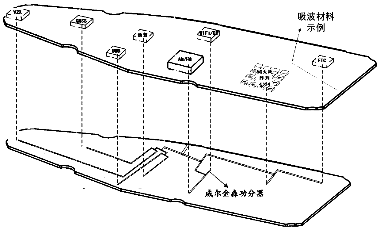
[0065] On the basis of adopting the above method 1 or method 2, a wave-absorbing material of a preset frequency band may also be provided on the adjacent side of each antenna among the plurality of antennas. Wherein, the adjacent side here may include upper side, lower side, left side and right side. It can be understood that the installation position of the absorbing material can be set according to the actual situation, for example, figure 2 A setting method of the absorbing material shown in , the absorbing material can be set on the lower side and the left side of the ETC signal transmitting and receiving antenna. It can be understood that since there is no adjacent antenna on the upper and right sides of the ETC signal transmitting and receiving antenna , in order to save cost, there is no need to set up the absorbing material.
[0066] In practical applications, the preset frequency band is the working frequency band of the antennas deployed adjacent to each antenna. ...
PUM
| Property | Measurement | Unit |
|---|---|---|
| Length | aaaaa | aaaaa |
| Thickness | aaaaa | aaaaa |
Abstract
Description
Claims
Application Information
 - R&D
- Intellectual Property
- Life Sciences
- Materials
- Tech Scout
- Unparalleled Data Quality
- Higher Quality Content
- 60% Fewer Hallucinations
Browse by: Latest US Patents, China's latest patents, Technical Efficacy Thesaurus, Application Domain, Technology Topic, Popular Technical Reports.
© 2025 PatSnap. All rights reserved.Legal|Privacy policy|Modern Slavery Act Transparency Statement|Sitemap|About US| Contact US: help@patsnap.com


