
Drilling tool with forcible entry function

A kind of function and drilling tool technology, which is applied in the field of drilling tools with demolition function, can solve the problems of single function, inability to dynamically adjust the expansion range, reduce the drilling efficiency of the drill bit, etc., and achieve the effect of improving efficiency

Pending Publication Date: 2022-02-15
JIANGSU WUXI MINERAL EXPLORATION MASCH GENERAL FAB CO LTD
View PDF0 Cites 0 Cited by
  • Summary
  • Abstract
  • Description
  • Claims
  • Application Information

AI Technical Summary

Problems solved by technology

[0002] Drilling tools refer to tools related to drilling and drilling, mainly including drilling tools and metallurgical furnace drilling tools. When drilling in a specific situation, when it needs to be demolished, it is necessary to use other tools to assist. The function is single, which reduces the practicability of the drilling tool
[0003] The traditional device has the following disadvantages: the existing drilling tools have some shortcomings in the use process, and can only drill for specific situations. Single, which reduces the practicability of the drilling tool. At the same time, the installation and disassembly of the drill bit is more cumbersome, prolonging the installation and disassembly cycle, and the current drilling tool has a small range of use, and the drill bit cannot be expanded during drilling. The range is dynamically adjusted, which reduces the drilling efficiency of the drill bit and increases the difficulty of the operation of the staff

Method used


Image

  • Drilling tool with forcible entry function
  • Drilling tool with forcible entry function
  • Drilling tool with forcible entry function

Examples


Embodiment Construction

[0028] The following will clearly and completely describe the technical solutions in the embodiments of the present invention with reference to the drawings in the embodiments of the present invention.

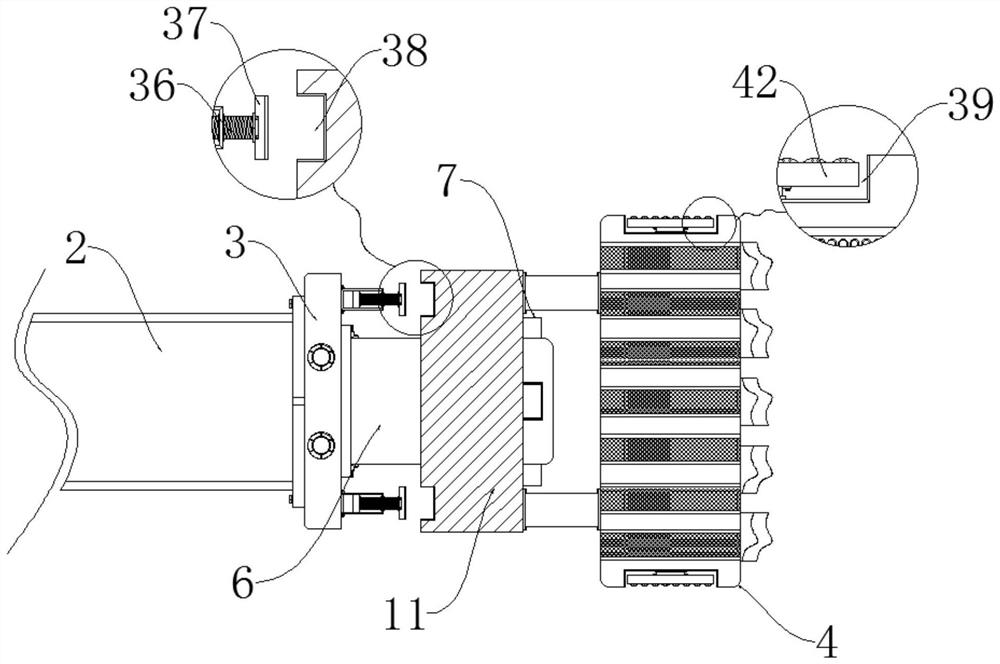
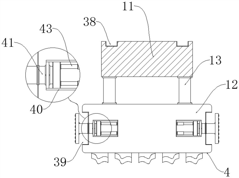
[0029] see Figure 1-8 , the present invention provides a technical solution: a drilling tool with a breakaway function, including a power source 1, a drill rod 2, a positioning plate 3, a drill body 4 and an impact rod body 5, and the drill rod 2 is installed on the power source 1 output end, the positioning disc 3 is installed at the tail of the drill pipe 2, the center of the lower surface of the positioning disc 3 is locked with a positioning column 6, and the bottom of the side walls around the positioning column 6 is equipped with a supporting component 7, so A positioning component 8 is installed in the middle of the side walls around the positioning column 6. The drill body 4 is sleeved outside the positioning column 6. The positioning component 8 is engaged with the d...


PUM


Abstract

The invention discloses a drilling tool with a forcible entry function. The drilling tool comprises a power source, a drill rod, a positioning disc, a drill bit body and an impact rod body, the drill rod is installed at the output end of the power source, the positioning disc is installed at the tail of the drill rod, a positioning column is installed at the center of the lower surface of the positioning disc in a locking mode, a bearing assembly is installed at the bottom of the side wall of the periphery of the positioning column, and a positioning assembly is installed in the middle of the peripheral side wall of the positioning column. The drill bit body and the impact rod body can be quickly mounted and dismounted through the bearing assembly and the positioning assembly, subsequent quick dismounting is facilitated while stable operation of the drill bit body and the impact rod body is guaranteed, the overall machining range of equipment is enlarged, when forcible entry is needed, the impact rod body can be quickly replaced, auxiliary operation can be conducted without the help of external tools, meanwhile, under the cooperation of a diameter expanding assembly, the drilling diameter can be expanded later, the rapid diameter expanding effect is achieved, and the drilling efficiency of the drilling tool is improved.

Description

technical field [0001] The invention relates to the related technical field of drilling tools, in particular to a drilling tool with a rescue function. Background technique [0002] Drilling tools refer to tools related to drilling and drilling, mainly including drilling tools and metallurgical furnace drilling tools. When drilling in a specific situation, when it needs to be demolished, it is necessary to use other tools to assist, the function is single, and the practicability of the drilling tool is reduced. [0003] The traditional device has the following disadvantages: the existing drilling tools have some shortcomings in the use process, and can only drill for specific situations. Single, which reduces the practicability of the drilling tool. At the same time, the installation and disassembly of the drill bit is more cumbersome, prolonging the installation and disassembly cycle, and the current drilling tool has a small range of use, and the drill bit cannot be expan...

Claims


Application Information

Patent Timeline
Patent Type & Authority Applications(China)
IPC IPC(8): E21B17/04E21B10/32E21B19/18
CPCE21B17/04E21B10/322E21B10/265E21B19/18
Inventor 刘长驰高伟强朱蓉洁
Owner JIANGSU WUXI MINERAL EXPLORATION MASCH GENERAL FAB CO LTD
Learn More