The transmission of the output shaft and the antenna device using the transmission can be selected

A transmission device and a technology for selecting output, applied in the direction of antenna, antenna parts, antenna support/installation device, etc., can solve the problems of high cost and large volume, and achieve the effect of light weight, lower antenna cost, and save the number of motors

Active Publication Date: 2022-08-05
中山市粤为科技有限公司
View PDF8 Cites 0 Cited by
  • Summary
  • Abstract
  • Description
  • Claims
  • Application Information

AI Technical Summary

Problems solved by technology

[0004] Aiming at the above-mentioned technical problems of using a motor to drive an antenna to adjust the posture in the prior art mentioned above, the cost is high and the volume is large

Method used


Image

  • The transmission of the output shaft and the antenna device using the transmission can be selected
  • The transmission of the output shaft and the antenna device using the transmission can be selected
  • The transmission of the output shaft and the antenna device using the transmission can be selected

Examples


Embodiment Construction

[0023] The embodiments of the present invention will be described in detail below with reference to the accompanying drawings.

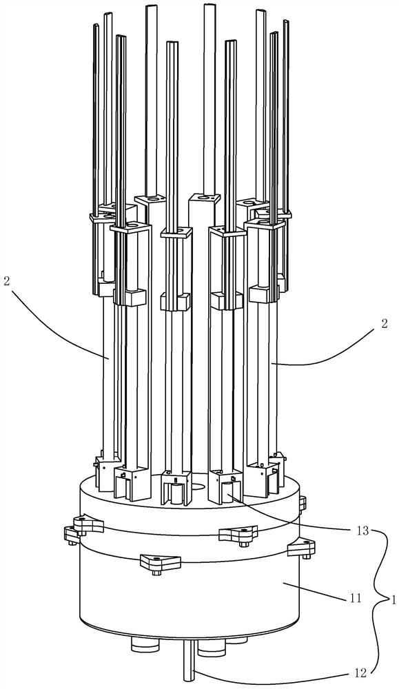
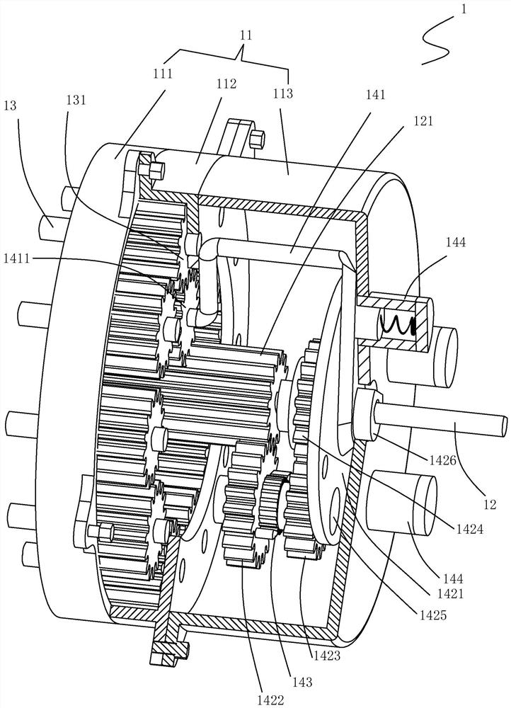
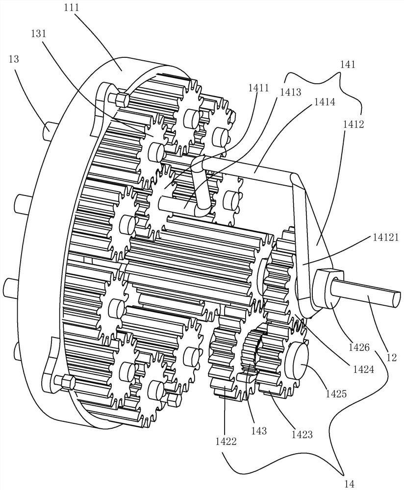
[0024] like Figure 2 to Figure 7 As shown, a transmission device that can select an output shaft in this embodiment, the transmission device 1 includes: a casing 11, an input shaft 12, at least two sets of output shafts 13 and a position selection transmission assembly 14; the input The shaft 12 and the output shaft 13 are rotatably connected to the housing 11 , the rotating shaft of the input shaft 12 and the rotating shaft of the output shaft 13 are parallel to each other, and the output shaft 13 is arranged at the center of the circle and the rotation center of the output shaft 13 is collinear On the arc, the input shaft 12 is provided with a gear A121, and the output shaft 13 is provided with a gear B131; the position selection transmission assembly 14 includes: a rotating frame 141, a transmission assembly 142 and a one-way transmission Compon...


PUM


Abstract

The invention discloses a transmission device capable of selecting an output shaft. When the input shaft rotates in a first rotation direction, the input shaft drives a rotating frame to rotate through a transmission assembly and a one-way transmission assembly until a transition gear can be connected with any group of output shafts. When the input shaft rotates in the second rotation direction opposite to the first rotation direction and the rotating frame is at the predetermined position, the input shaft is driven by gear A, transition gear and gear B The corresponding output shaft rotates and outputs; that is to say, through the input shaft along the first rotation direction, the transition gear is driven to rotate to mesh with the gear B on the selected output shaft; through the input shaft along the second rotation direction, the input shaft passes through the gear A. , The meshing between the transition gear and the gear B can drive the output shaft to rotate, that is, only one motor is needed to drive different output shafts to rotate independently.

Description

technical field [0001] The invention relates to a transmission device that can select an output shaft, and also relates to an antenna device. Background technique [0002] In the mobile communication technology, the radiation angle of the base station antenna needs to be adjusted to cover different mobile communication areas, and the antenna is usually adjusted by using an antenna transmission mechanism. The antenna adjustment drive mechanism has a significant impact on the cost, weight and size of the antenna. At present, most of the base station antennas on the market are a set of motors (including a servo motor and a corresponding driver) to drive an antenna to act alone. To realize the independent adjustment of multiple antennas, it is necessary to configure motors equal to the number of antennas. Due to the high price of motors , resulting in a bulky and expensive antenna. [0003] The present invention is researched and proposed for the deficiencies of the prior art....

Claims


Application Information

Patent Timeline
Patent Type & Authority Patents(China)
IPC IPC(8): H01Q3/02H01Q1/24
CPCH01Q3/02H01Q1/246
Inventor 王斌龙亿钟欢欢朱树聘
Owner 中山市粤为科技有限公司
Why Eureka
Try Eureka