Communication equipment for video monitoring system

A video surveillance system and communication technology, used in closed-circuit television systems, supporting machines, cooling/ventilating/heating renovations, etc., can solve the inconvenience of quick disassembly and installation of communication equipment, and the insufficient connection between monitoring cables and communication equipment wiring ports. and other problems, to achieve the effect of isolating dust from entering, avoiding excessive temperature and improving stability

Pending Publication Date: 2022-02-15
苏州万鼎豪鑫科技有限公司
View PDF0 Cites 1 Cited by
  • Summary
  • Abstract
  • Description
  • Claims
  • Application Information

AI Technical Summary

Problems solved by technology

[0005] Aiming at the deficiencies of the prior art, the present invention provides a communication device for a video monitoring system, which solves the inconvenience of rapid disassembly and installation of the existing communication equipment during maintenance, and the plugging of the monitoring connection line and the connection port of the communication equipment The problem of not being strong enough

Method used


Image

  • Communication equipment for video monitoring system
  • Communication equipment for video monitoring system
  • Communication equipment for video monitoring system

Examples


Embodiment 1

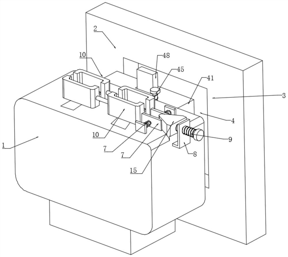
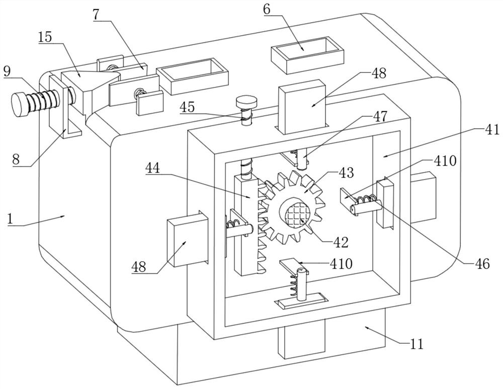
[0027] Embodiment 1: A communication device for a video monitoring system, comprising a communication device 1 and a mounting plate 2, the front end of the mounting plate 2 is provided with a groove 3, and the groove wall of the groove 3 is symmetrically provided with a slot 5 for communication. The rear end face of the device 1 is equipped with a mounting mechanism 4, the upper end face of the communication device 1 is symmetrically provided with a socket 6, the right side wall of the communication device 1 is fixedly connected with a threaded plate 8, and the side wall of the threaded plate 8 is threaded through the threaded connection. Rod 9, the upper end surface of communication equipment 1 is connected with rubber jacket 10 through chute and sliding block symmetrical sliding connection, and the right side wall of rubber jacket 10 located on the right side is symmetrically fixedly connected with oblique plate 7, and the upper surface of communication equipment 1 The end su...

Embodiment 2

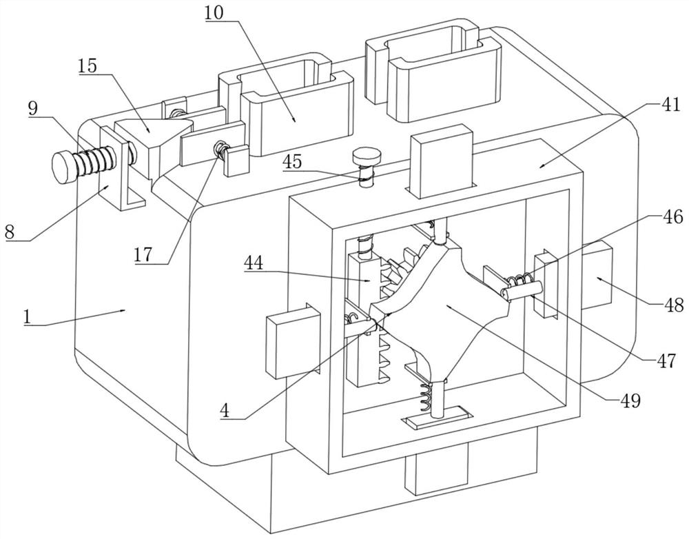
[0028]Embodiment 2: The difference between this embodiment and Embodiment 1 is that the installation mechanism 4 includes an installation frame 41, a rotating shaft 42, a gear 43, a rack 44, a threaded column 45, a limit spring 46, a support column 47, an inserting plate 48, The cam turntable 49, the support plate 410, the rear end surface of the communication equipment 1 is fixedly connected with the installation frame 41, the rear end surface of the communication equipment 1 is connected with the gear 43 through the rotating shaft 42, the outer wall of the gear is meshed with a rack 44, and the upper end surface of the rack 44 Rotate and connect the threaded post 45, the threaded post 45 is threadedly connected with the upper chamber wall of the installation frame 41, the rack 44 is slidably connected with the inner chamber wall of the installation frame 41, the front end surface of the rotating shaft 42 is fixedly connected with a cam turntable 49, and the installation frame ...


PUM


Abstract

The invention discloses communication equipment for a video monitoring system. The communication equipment comprises a communication device and a mounting plate, the front end face of the mounting plate is provided with a groove, the groove wall of the groove is symmetrically provided with slots, the rear end face of the communication device is provided with a mounting mechanism, and the upper end face of the communication device is symmetrically provided with plug ports. A threaded plate is fixedly connected to the right side wall of the communication device, inclined plates are symmetrically and fixedly connected to the right side wall of the rubber jacket located on the right side, a triangular plate is slidably connected to the upper end face of the communication device, a supporting frame is fixedly connected to the lower end face of the communication device, a flat plate is fixedly connected to the inner cavity wall of the supporting frame, and the lower end face of the flat plate is fixedly connected with a small motor. The invention relates to the technical field of communication devices. The communication equipment for the video monitoring system solves the problems that the existing communication device is inconvenient to disassemble and assemble quickly during maintenance, and the plugging between the monitoring connecting line and the wiring port of the communication equipment is not firm enough.

Description

technical field [0001] The invention relates to the technical field of communication equipment, in particular to a communication equipment used in a video surveillance system. Background technique [0002] Video surveillance includes front-end cameras, transmission cables, and video surveillance platforms. Cameras can be divided into network digital cameras and analog cameras, which can be used as front-end video image signal acquisition. A complete video surveillance system is composed of camera, transmission, control, display, record registration 5 major components, the camera transmits the video image to the control host through the network cable or coaxial video cable, and the control host then distributes the video signal to each monitor and video recording device Analyze transmissions, etc. [0003] The existing communication equipment is inconvenient to be quickly disassembled and installed during maintenance, which causes inconvenience to the maintenance, and the co...

Claims


Application Information

Patent Timeline
IPC IPC(8): H04N7/18F16M11/04H05K7/20
CPCH04N7/18F16M11/041H05K7/20136
Inventor 田欣
Owner 苏州万鼎豪鑫科技有限公司
Why Eureka
Try Eureka