
Hand grinder coupler structure

A technology for connecting structures and grinding wheels, which is applied to the device for fixing grinding wheels, parts of grinding machine tools, grinding machines, etc. It can solve the problems of operator inconvenience and unloading, and achieve the effect of improving efficiency and reducing the unit price of production

Pending Publication Date: 2022-02-15
EMK CO LTD
View PDF3 Cites 0 Cited by
  • Summary
  • Abstract
  • Description
  • Claims
  • Application Information

AI Technical Summary

Problems solved by technology

In such a structure, since the fixed bracket on the rotating shaft needs to be screwed to fasten the connecting disk bracket, not only is there the trouble of removing the disk bracket or re-fastening it during the operation, but also it is necessary to make an additional brake. The unit is running, so it brings considerable inconvenience to the operator

Method used


Image

  • Hand grinder coupler structure
  • Hand grinder coupler structure
  • Hand grinder coupler structure

Examples


Embodiment Construction

[0021] Hereinafter, preferred embodiments according to the present invention will be described in detail with reference to the accompanying drawings, but the characteristic structures and functions thereof are shown as an example of configuration, and therefore are not limited to the embodiments described in this specification.

[0022] First, the technology disclosed in Korean Patent Laid-Open Publication No. 10-0973157 will be described in detail as a preferred example of application of the present invention, and the problems caused by it will be deduced, and then the structure and effects of the present invention will be described later.

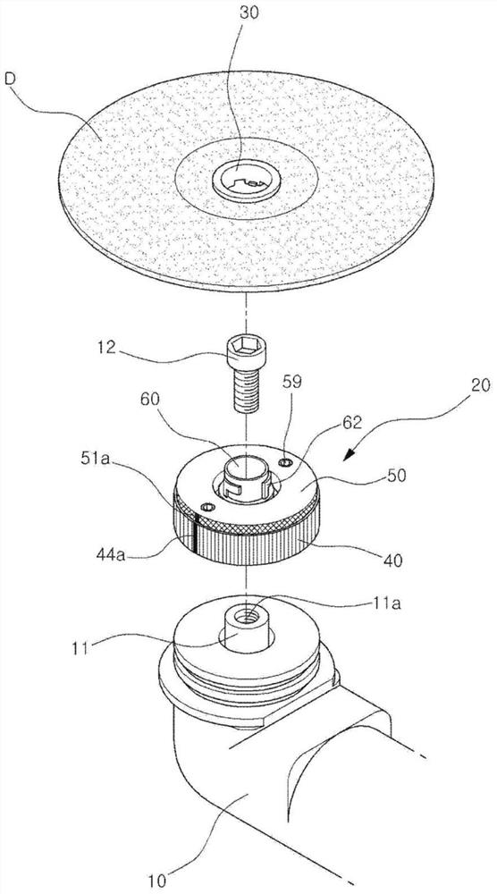
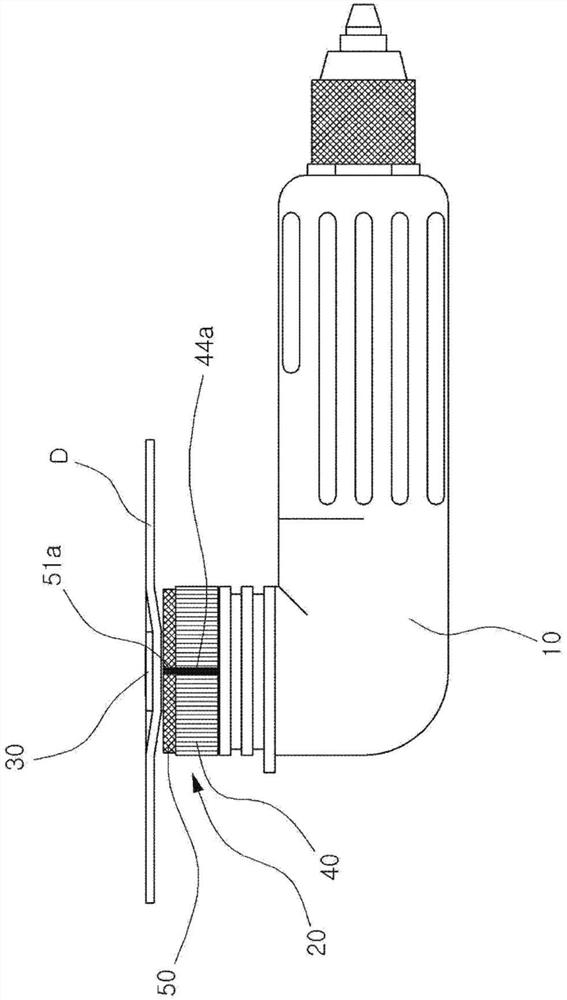
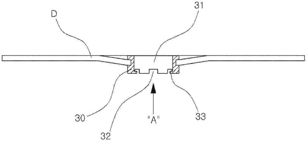
[0023] like Figure 1 to Figure 11 As shown, the manual grinding wheel is composed of a power coupling unit 20 including a normal grinding wheel main body 10 and a disc holder 30 in which a disc D is integrally mounted.

[0024] A rotating shaft 11 having a threaded hole 11a is provided at one front end of the grinding wheel body 10 to be...


PUM


Abstract

The present invention relates to a hand grinder coupler structure that can more simply and quickly attach / detach a machining disk coupled to a rotary shaft of a grinder main body so as to be used for polishing the surface of an object to be machined, trimming, cutting or the like. The present invention simplifies a linking component of a coupler mounted on the rotary shaft of the grinder main body, so that manufacturing costs can be greatly reduced, and enables the consumable disk to be easily attached to or detached from the coupler with one touch so that a replacement operation is quickly performed during machining, and thus efficiency can be greatly improved.

Description

technical field [0001] The present invention relates to a connection structure of a hand grinder, which can be used for grinding, cutting, cutting, etc. Easy and quick disassembly. Background technique [0002] Generally, hand grinders are used to smooth the rough surface of processed parts or parts to be painted, or to partially cut raw materials such as pipes, angle steel, and iron plates. That is, the hand grinder is driven by an electric motor or the air pressure generated by the operation of a compressor (compressor), while the rotary shaft is rotated at high speed, and the surface of the object is ground with a consumable disc, thereby grinding the unfinished part. , corners and other grinding or cutting operations. In the case of the above-mentioned discs, the grindstone or sandpaper is easily worn out together with the surface to be chamfered, so it needs to be replaced frequently in a state where a large number of discs are prepared, so improvements are being made...

Claims


Application Information

Patent Timeline
IPC IPC(8): B24B45/00
CPCB24B45/006B24B23/022B24B45/003
Inventor 权纯彻
Owner EMK CO LTD
Learn More