Medical diagnosis bed device and medical image diagnosis device
A technology for diagnosis and placement, which is applied to patient positioning for diagnosis, instruments for radiological diagnosis, diagnosis, etc., can solve the problems of large scanning room space, occupation, transportation and setting difficulties, etc. The effect of reducing the size and increasing the available space
- Summary
- Abstract
- Description
- Claims
- Application Information
AI Technical Summary
Problems solved by technology
Method used
Image
Examples
Embodiment approach 1
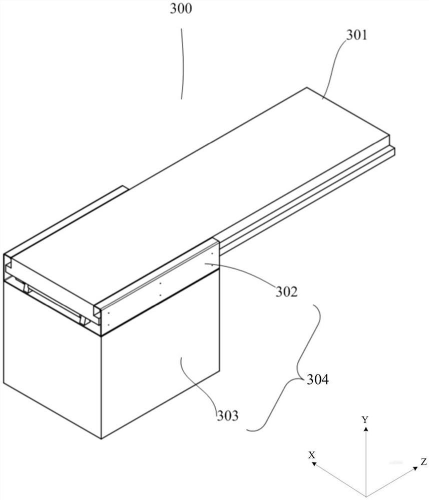
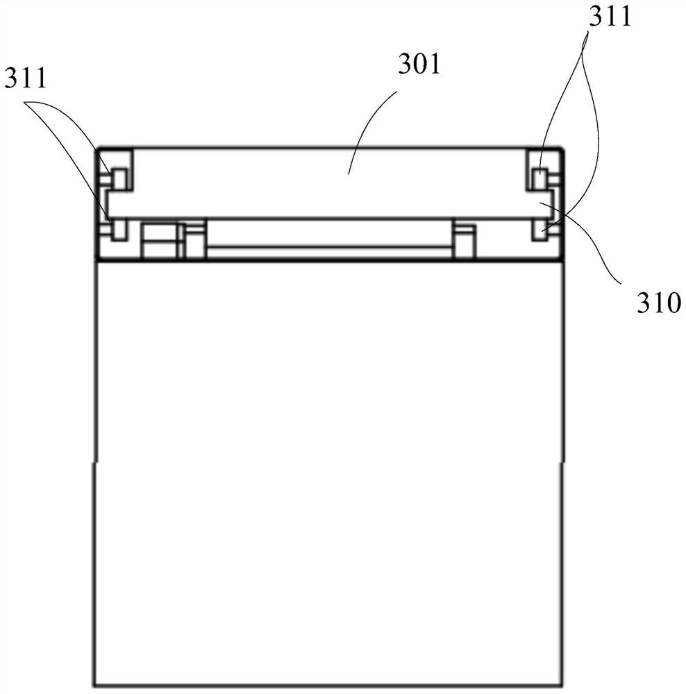
[0038] figure 1 It is a schematic perspective view of the medical bed apparatus of Embodiment 1. figure 2 It is a schematic front view of the medical bed apparatus according to the first embodiment.
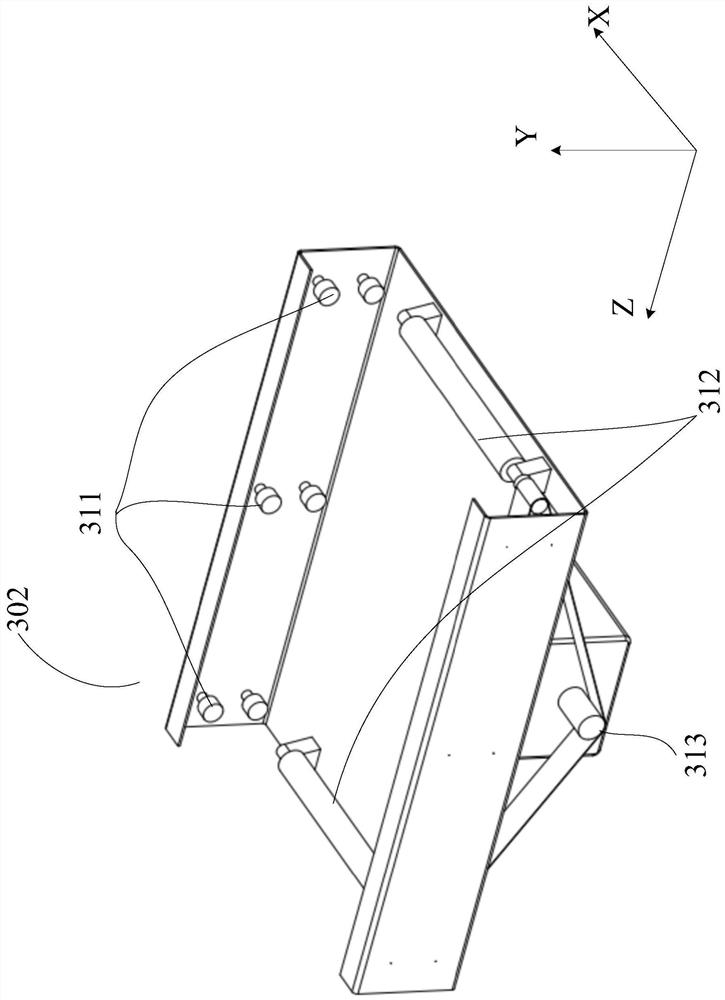
[0039] Such as figure 1 As shown, the medical bed apparatus 300 includes: a top board 301 for placing the subject and detachably assembled with respect to the top board driving support part 302; a top board driving support for supporting the top board 301 and moving it along the longitudinal direction part 302; and a base 303 which is installed on the ground and supports the top plate driving support part 302 from below. The base 303 is a casing having a motor and the like inside.
[0040] exist figure 1 It is shown that the dimension of the longitudinal direction of the top plate driving support part 302 is consistent with the dimension of the longitudinal direction of the base 303 , but the two may not be consistent. The top drive support portion 302 and the base 303 togeth...
Embodiment approach 2
[0065] Figure 7 It is a schematic front view of a top drive support unit used in the medical bed apparatus of Embodiment 2.
[0066] Embodiment 2 differs from Embodiment 1 in that sliders are used instead of rollers as supports for the top plate 301 . The rest of the configuration is the same as that of Embodiment 1, and thus redundant descriptions will be omitted.
[0067] In Embodiment 2, vertically opposed paired sliders 314 are respectively provided on the left and right side walls of the top plate driving support portion. If the vertically opposed paired sliders 314 are called a pair of sliders, Then at least one set of paired slide blocks is respectively arranged at the front and rear end portions of the left and right side walls of the top plate driving support portion. A lubricating material is adhered to the surface of each slider on the side opposite to the protruding portion of the top plate 301 , and the slider comes into contact with the protruding portion of t...
Embodiment approach 3
[0070] Embodiment 1 simply illustrates the process of the top board being inserted or pulled out relative to the top board driving support to complete the loading and unloading process, and embodiment 3 provides a specific top board loading and unloading method.
[0071] According to Embodiment 3, positioning and monitoring of the position of the top plate can be easily performed.
[0072] Figure 8 It is a diagram schematically showing the relative positional relationship between the main body of the bed and the stand when the top plate with the mechanical stopper is attached to the main body of the bed, Figure 8 The rigging device is shown in abbreviated drawing.
[0073] In Embodiment 3, such as Figure 8 As shown, the rear end of the top plate has a mechanical stop, such as Figure 9 As shown, a blocking portion is provided at the rear end portion of the top plate driving support portion, that is, the end portion away from the stand side, and at a position correspondin...
PUM
 Abstract
Description
Claims
Application Information
 - R&D Engineer
- R&D Manager
- IP Professional
- Industry Leading Data Capabilities
- Powerful AI technology
- Patent DNA Extraction
Browse by: Latest US Patents, China's latest patents, Technical Efficacy Thesaurus, Application Domain, Technology Topic, Popular Technical Reports.
© 2024 PatSnap. All rights reserved.Legal|Privacy policy|Modern Slavery Act Transparency Statement|Sitemap|About US| Contact US: help@patsnap.com


