Side head placing device convenient for replacing side milling cutter head

The technology of a side milling cutter and a boss is applied in the field of side head placement devices, which can solve the problems of operator scratches, reduced safety, and easy accidental touch, etc., to achieve high safety, improve protection effect, and protect unsafe hidden dangers. Effect

Pending Publication Date: 2022-02-18
天津巴泰克机械制造有限公司
View PDF0 Cites 0 Cited by
  • Summary
  • Abstract
  • Description
  • Claims
  • Application Information

AI Technical Summary

Problems solved by technology

[0003] In the CNC milling machine of the prior art, the tool needs to be placed in the tool head holder for storage, but because the existing tool holder lacks the blocking effect on the tool, the tool is easily bumped by the outside during the machining process, resulting in damage. In the process of manual tool change, accidental touches are prone to occur, causing the operator's hands to be scratched by the tool, thereby reducing safety

Method used


Image

  • Side head placing device convenient for replacing side milling cutter head
  • Side head placing device convenient for replacing side milling cutter head

Examples


Embodiment 1

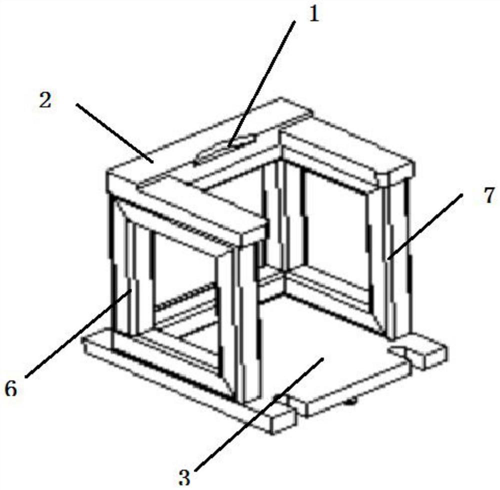
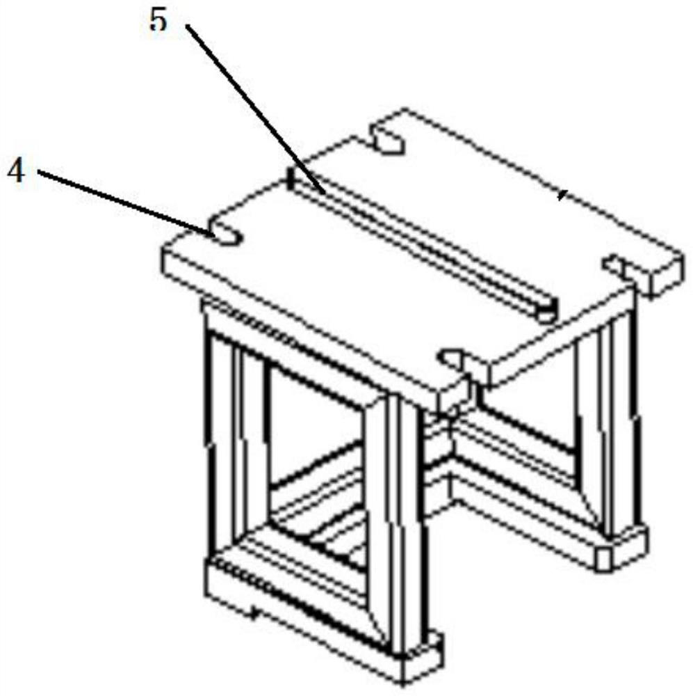
[0011] A side head placement device for easy replacement of side milling cutter heads, which is characterized in that it includes a boss 1, a front frame 2, a bottom plate 3, a left frame 6, and a right frame 7. The top of the boss 1 is installed with a front frame 2 through bolts, and the boss The left end of the top of platform 1 is equipped with a left frame 6 through bolts, and the right end of the top of the boss 1 is equipped with a right frame 7 through bolts. The front frame 2, left frame 6, and right frame 7 form a three-sided structure; the top of the front frame 2 is provided with a boss 1. The boss 1 is an arc-shaped structure, the bottom of the bottom plate 3 is provided with limiting grooves 5, and the front and rear ends of the bottom plate 3 are respectively provided with limiting grooves 5.

Embodiment 2

[0013] Before the present invention is used, when assembling the front frame 2, the left frame 6, the right frame 7, and the bottom plate 3, it is necessary to ensure that the welding bead at the joint is complete and smooth, and there is no air hole and slag inclusion, so as to avoid the occurrence of tooling on the side milling cutter head due to shape defects Secondary damage, the front and rear ends of the bottom plate 3 are designed with card slots 4 and the middle of the bottom plate 3 is designed with the limit groove 5 for positioning to ensure that it is fixed with the bottom plate 3 without shaking. The boss 1 on the top of the front frame 2 has a radian design to fit the side milling cutter The shape of the head is surrounded by a three-sided frame, which can more effectively protect the hidden dangers caused by the side milling cutter head during processing. Frame 2, left frame 6, and right frame 7 limit the position of the hand to prevent the operator from touching...


PUM


Abstract

The invention discloses a side head placing device convenient for replacing a side milling cutter head. The side head placing device is characterized by comprising a boss, a front frame, a bottom plate, a left frame and a right frame; the front frame is mounted at the top of the boss through a bolt, the left frame is mounted at the left end of the top of the boss through a bolt, and the right frame is mounted at the right end of the top of the boss through a bolt; the boss is arranged at the top of the front frame, limiting grooves are formed in the bottom of the bottom plate, and the limiting grooves are formed in the front end and the rear end of the bottom plate correspondingly, so that the protection effect on a cutter is greatly improved through the design, and safety is high.

Description

technical field [0001] The invention relates to the technical field of numerical control machining centers, in particular to a side head placement device for easy replacement of side milling cutter heads. Background technique [0002] Machining centers are developed from CNC milling machines. The biggest difference from the CNC milling machine is that the machining center has the ability to automatically exchange machining tools. By installing different-purpose tools on the tool magazine, the machining tool on the spindle can be changed through an automatic tool changer in one clamping to achieve a variety of machining. Function; [0003] In the CNC milling machine of the prior art, the tool needs to be placed in the tool head holder for storage, but because the existing tool holder lacks the blocking effect on the tool, the tool is easily bumped by the outside during the machining process, resulting in damage. In the process of manual tool change, accidental touches are p...

Claims


Application Information

Patent Timeline
IPC IPC(8): B23C9/00B23Q13/00
CPCB23C9/00B23Q13/00
Inventor 袁志国
Owner 天津巴泰克机械制造有限公司
Why Eureka
Try Eureka