Machining method for tubular part with runner groove

A technology for parts processing and runner grooves, which is applied in the field of tubular parts processing with runner grooves, can solve problems such as deformation of tubular parts, and achieve the effects of reducing deformation, reducing blank deformation, and ensuring dimensional accuracy.

Pending Publication Date: 2022-02-18
HUBEI SANJIANG AEROSPACE GRP HONGYANG ELECTROMECHANICAL
View PDF10 Cites 0 Cited by
  • Summary
  • Abstract
  • Description
  • Claims
  • Application Information

AI Technical Summary

Problems solved by technology

[0003] The purpose of this application is to at least to a certain extent solve the technical problem that the existing processing technology processes the flow channel groove on the outer wall of the tubular part and easily deforms the tubular part. Therefore, the application provides a tubular part with a flow channel groove processing methods

Method used


Image

  • Machining method for tubular part with runner groove
  • Machining method for tubular part with runner groove
  • Machining method for tubular part with runner groove

Examples


Embodiment 1

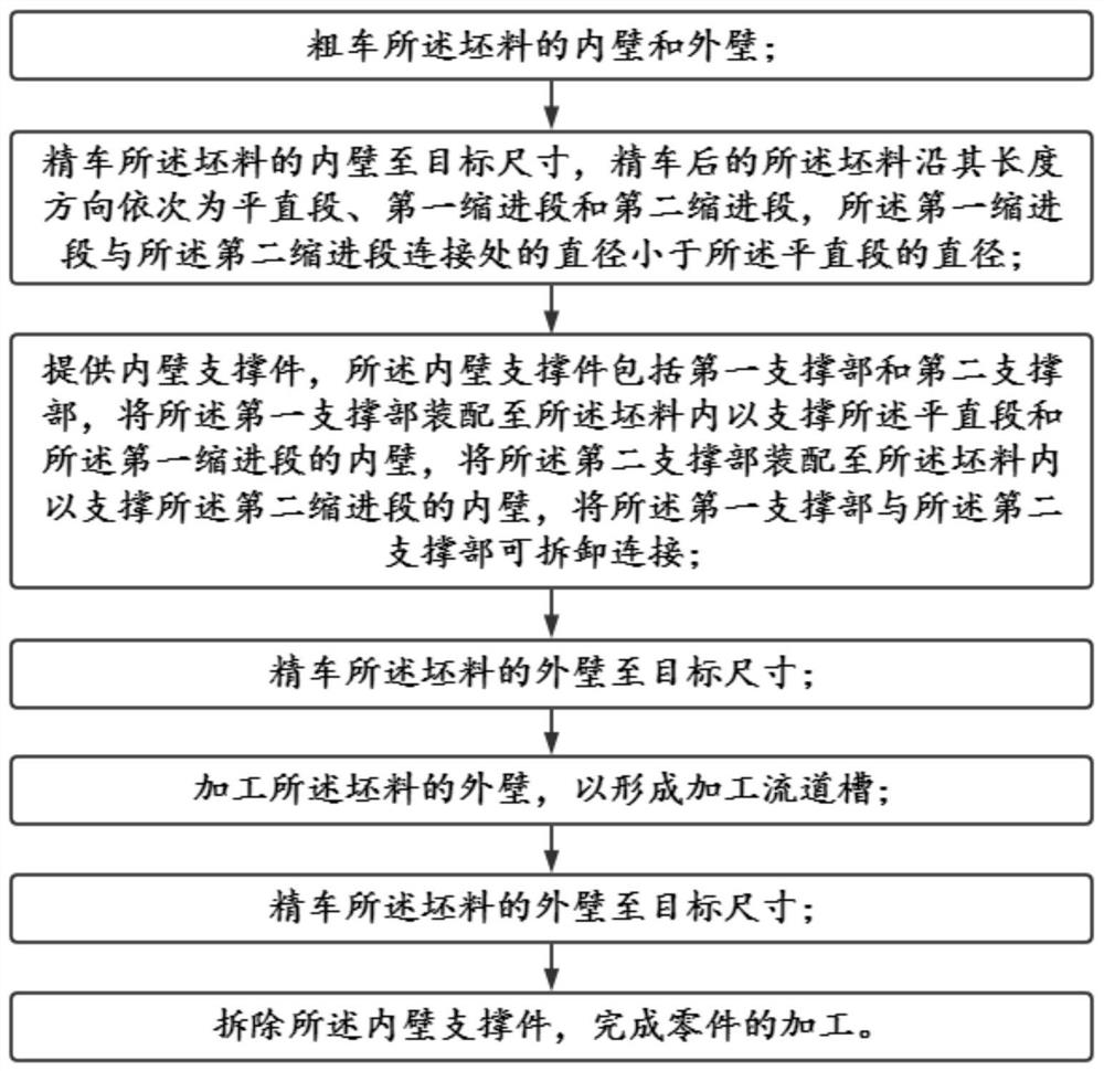
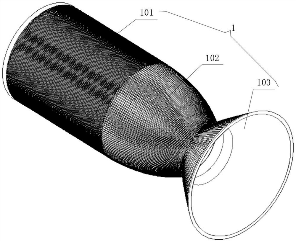
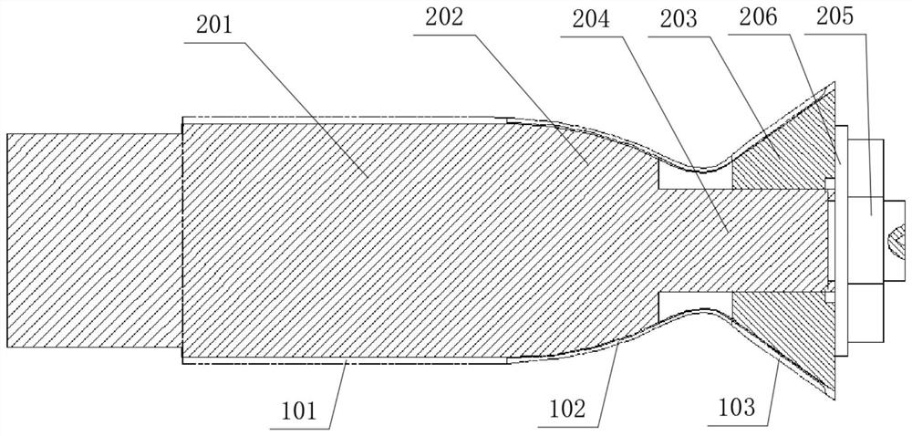
[0035] like Figure 1-Figure 4 As shown, this embodiment provides a method for processing a tubular part with runner grooves, which is used to process a blank into a tubular part 1. The part 1 is a straight section 101, a first indentation section 102 and a second indentation section in sequence. Into the section 103, the diameter of the junction of the first indented section 102 and the second indented section 103 is smaller than the diameter of the straight section 101, and the inner diameter of the straight section 101 is the same along its axial direction, the first indented section 102 and the second indented section 102 The two indented sections 103 are both funnel-shaped, and the opening ends with larger diameters are in opposite directions. It can be understood that referring to figure 2 , Part 1 has a neck, and the diameters of the pipe body on both sides of the neck are larger than the diameter of the neck. The pipe wall of the pipe body of Part 1 is generally thinn...

Embodiment 2

[0057] On the basis of Example 1, this embodiment discloses a specific implementation of a method for processing a tubular part 1 with a runner groove 104. In this embodiment, the blank is a copper alloy, and the wall thickness of the target size of the part 1 is 4.8mm, the inner diameter of the neck is Φ96, 288 grooves with a uniform rib width of 0.9±0.1mm, 144 grooves with a rib width of 1.3±0.1mm and 1.6±0.1mm each, and the remaining wall thickness of the groove is 0.8±0.1mm.

[0058] After rough turning the blank in step 1, in step 2, the inner hole of the neck of the rough turning is Φ90mm, and the unilateral margin of the end face is 10mm. The outer wall of the blank is clamped by the lathe, and the inner hole is aligned within Φ0. The steps of turning, semi-finishing and finishing turning process the inner wall of the straight section 101 and the inner wall of the first indented section 102 of the target size, and the unilateral margin of the end surface is 5 mm. After ...


PUM


Abstract

The invention discloses a machining method for a tubular part with a runner groove, belongs to the technical field of machining, and solves the technical problem that the tubular part is easy to deform when the runner groove is machined on the outer wall of the tubular part in the existing machining technology. The machining method comprises the following steps that: the inner wall and the outer wall of a blank are roughly turned, and most machining allowance on the surface of the blank is cut off; the inner wall of the blank is subjected to finish turning to a target size, and the blank subjected to finish turning sequentially comprises a straight section, a first retraction section and a second retraction section; an inner wall supporting piece is provided, the inner wall supporting piece comprises a first supporting part and a second supporting part, the first supporting part is assembled into the blank to support the inner wall of the straight section and the inner wall of the first retraction section, and the second supporting part is assembled into the blank to support the inner wall of the second retraction section; the outer wall of the blank is finely turned to a target size; the runner groove is machined; and the inner wall supporting piece is dismantled, and part machining is completed. Blank deformation can be reduced, the size precision of the runner groove is guaranteed, and the product quality is guaranteed.

Description

technical field [0001] The invention belongs to the technical field of mechanical processing, and in particular relates to a processing method for a tubular part with flow channel grooves. Background technique [0002] Liquid rocket engine technology is an important basis for the development of liquid launch vehicles. The inner wall is an important component of the thrust chamber of the liquid engine. The inner wall is a tubular part. The outer wall of this tubular part is not straight. Its contour is complex, the material is special, and the rigidity of the thin-walled structure is poor. , the processing process is easily deformed, which makes it difficult for the existing processing technology to guarantee the accuracy of the cooling grooves distributed on the outer wall of the tubular part and the quality of the tubular part. Contents of the invention [0003] The purpose of this application is to at least to a certain extent solve the technical problem that the existin...

Claims


Application Information

Patent Timeline
Patent Type & Authority Applications(China)
IPC IPC(8): B23P15/00B23Q3/00
CPCB23P15/00B23Q3/00B23Q2703/10
Inventor 赵李萍谢萍张守明胡升谋梅力方文斌
Owner HUBEI SANJIANG AEROSPACE GRP HONGYANG ELECTROMECHANICAL
Why Eureka
Try Eureka