Automatic clamping and positioning mechanism suitable for multiple types of connecting rods

A technology of automatic clamping and positioning mechanism, used in positioning devices, clamping, metal processing mechanical parts, etc., can solve the problems of rotary offset of turntable, low positioning accuracy, single applicable products, etc., to ensure positioning accuracy, improve The effect of positioning accuracy

Pending Publication Date: 2022-02-18
FOSHAN PRATIC CNC SCI & TECH
View PDF0 Cites 1 Cited by
  • Summary
  • Abstract
  • Description
  • Claims
  • Application Information

AI Technical Summary

Problems solved by technology

[0004] The problem to be solved by the present invention is to provide an automatic clamping and positioning mechanism for connecting rods suitable for various varieties, which solves the problem that the existing clamping mechanism cannot realize the automatic clamping function, and the positioning depends on the shape, so the fixture needs to be replaced when the production is changed. Positioning, suitable for a single product; the positioning accuracy is not high, and the turntable will shift when it rotates, and the technical problem is that the loading position rotates to the processing position

Method used


Image

  • Automatic clamping and positioning mechanism suitable for multiple types of connecting rods
  • Automatic clamping and positioning mechanism suitable for multiple types of connecting rods
  • Automatic clamping and positioning mechanism suitable for multiple types of connecting rods

Examples


Embodiment Construction

[0022] The following will clearly and completely describe the technical solutions in the embodiments of the present invention with reference to the accompanying drawings in the embodiments of the present invention. Obviously, the described embodiments are only some, not all, embodiments of the present invention. Based on the embodiments of the present invention, all other embodiments obtained by persons of ordinary skill in the art without creative efforts fall within the protection scope of the present invention.

[0023] Specific examples are given below.

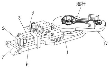
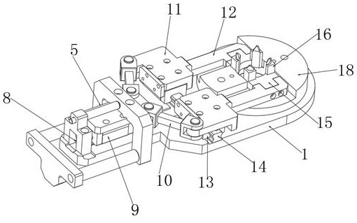
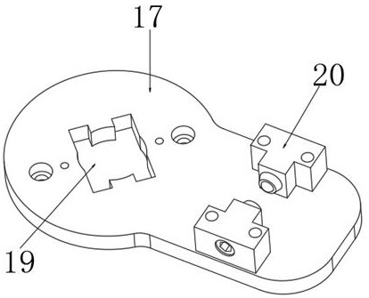
[0024] see Figure 1~Figure 3 , an automatic clamping and positioning mechanism for connecting rods applicable to many varieties, including a base plate 1, a first slide plate 5 is slidably installed on one end of the top side of the base plate 1, and a U-shaped seat 4 is installed on the top side of the first slide plate 5, the first slide plate 5 and one end of two linkage rods 10 are rotated and installed, and the two...


PUM


Abstract

The invention relates to an automatic clamping and positioning mechanism suitable for multiple types of connecting rods. The automatic clamping and positioning mechanism comprises a bottom plate, wherein a first sliding plate is slidably mounted at one end of the top side of the bottom plate, a U-shaped base is mounted on the top side of the first sliding plate, the first sliding plate and one ends of two linkage rods are rotatably mounted, the two linkage rods are symmetrically arranged, the other ends of the two linkage rods are rotationally installed with two symmetrically-arranged second sliding plates correspondingly, a fixing base is installed at the other end of the top side of the bottom plate, a workpiece positioning plate used for fixing a connecting rod workpiece is installed on the fixing base, and a positioning groove is formed in the workpiece positioning plate. Inner hole positioning is adopted for the connecting rod workpiece, the maximum stroke amount is adjusted according to different hole diameters, namely the moving stroke amount of a stretching claw is adjusted, and the automatic clamping and positioning mechanism is suitable for machining of multiple types of connecting rod workpieces; an inner hole four-claw centering tensioning structure is adopted, and a centering pressing structure is additionally arranged at the small end of the connecting rod workpiece, so that the product positioning precision is greatly improved; and when a rotary table rotates at a high speed in the machining process, the positioning precision can be guaranteed.

Description

technical field [0001] The invention relates to the technical field of auto parts processing, in particular to an automatic clamping and positioning mechanism for multi-variety connecting rods. Background technique [0002] Connecting rods are used as auto parts, and they need to be fixed by clamping mechanism during processing. [0003] The existing clamping mechanism cannot realize the automatic clamping function and relies on the shape positioning, so the fixture needs to be replaced when changing production. The processing position is rotated. Contents of the invention [0004] The problem to be solved by the present invention is to provide an automatic clamping and positioning mechanism for connecting rods suitable for various varieties, which solves the problem that the existing clamping mechanism cannot realize the automatic clamping function, and the positioning depends on the shape, so the fixture needs to be replaced when the production is changed. Positioning,...

Claims


Application Information

Patent Timeline
Patent Type & Authority Applications(China)
IPC IPC(8): B23Q3/08
CPCB23Q3/08
Inventor 孟祥东黄敏波沈成辉刘国锦林禄生
Owner FOSHAN PRATIC CNC SCI & TECH
Why Eureka
Try Eureka