
Multi-degree-of-freedom connecting device

A technology of connection device and degree of freedom, which is applied in the direction of drilling equipment, earthwork drilling, drill pipe, etc., can solve the problems that the center of the flow channel cannot be aligned, the time and cost of disassembly and assembly will increase, and the investment of considerable manpower and time will be achieved. The effect of reducing risk level and increasing work efficiency

Pending Publication Date: 2022-02-18
SUZHOU DAWSON DRILLING EQUIP CO LTD
View PDF0 Cites 0 Cited by
  • Summary
  • Abstract
  • Description
  • Claims
  • Application Information

AI Technical Summary

Problems solved by technology

[0002] In oil and natural gas well sites, the fluid composition is complex, and manifolds with multiple functions are usually required for joint operation. Due to the unevenness of the site, there are problems that the center of the flow channel cannot be aligned and the sealing surfaces cannot be effectively bonded between the manifolds. In the current field operations, Basically, the connection between manifolds is realized by multiple positioning and temporary leveling of the site; therefore, the disassembly and assembly of manifolds requires a lot of manpower and time, and with the increase of wellhead pressure, the weight of manifolds doubles, resulting in disassembly and assembly. The time and cost are also doubled; especially in well sites with a pressure close to 100MPa, the weight of a single manifold often reaches more than 10 tons. Due to the repeated lifting of the crane and the motion inertia of the manifold, the entire installation operation is time-consuming and labor-intensive and poses safety risks.

Method used


Image

  • Multi-degree-of-freedom connecting device
  • Multi-degree-of-freedom connecting device
  • Multi-degree-of-freedom connecting device

Examples


Embodiment 1

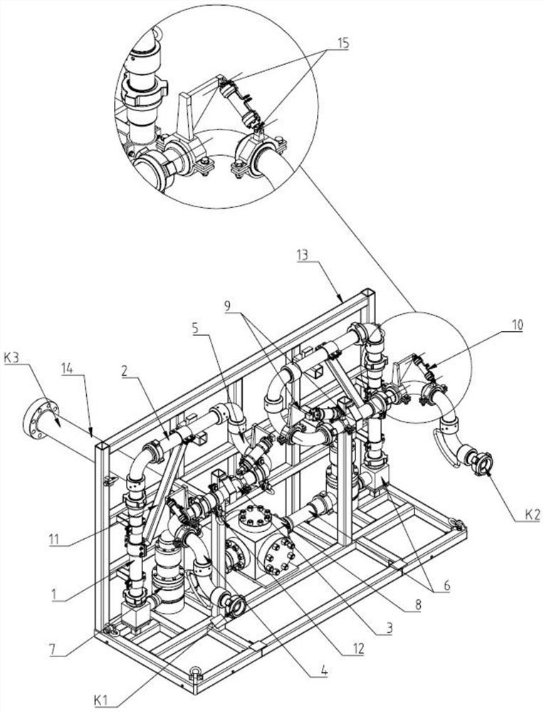
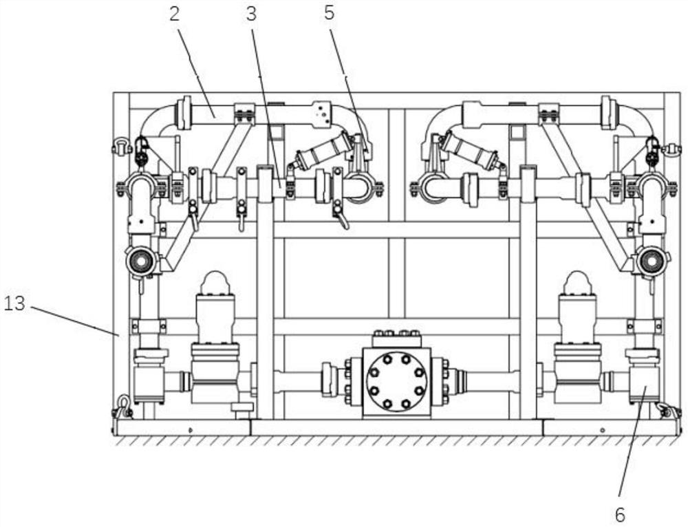
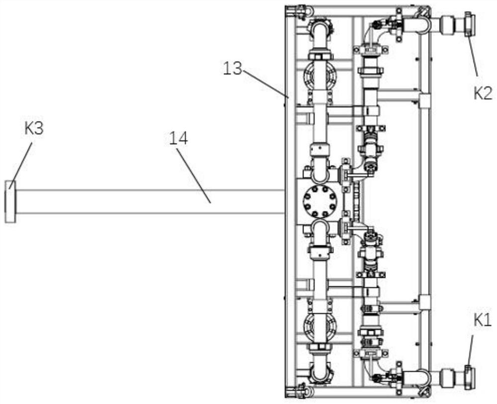
[0022] This embodiment provides a specific structure of a multi-degree-of-freedom connection device, such as Figure 1-3 As shown, including frame 13, multi-free movable arm, high-pressure pipeline 6, cock valve 7, diverter 8, flange pipe 14, wherein:

[0023] Multiple freely movable arms, high pressure pipeline 6, cock valve 7, diverter 8 and flange pipe 14 are all installed on the frame 13;

[0024] The multi-free movable arm is assembled by the first pipe body 1, the main movable pipe body 2, the secondary movable pipe body 3, the tail pipe body 4 and the transition pipe body 5, the head pipe body 1, the main movable pipe body 2, the transition pipe body 5, the secondary The movable pipe body 3 and the tail pipe body 4 are connected end to end to form multiple free movable arms;

[0025] The multi-free movable arm is connected to the high-pressure pipeline 6 through the plug valve 7 to form a movable fluid channel, and the flange tube 14 independently forms a fixed fluid c...

Embodiment 2

[0027] This embodiment provides a specific structure of a multi-degree-of-freedom connection device, such as Figure 1-3 As shown, including frame 13, multi-free movable arm, high-pressure pipeline 6, cock valve 7, diverter 8, flange pipe 14, wherein:

[0028] Multiple freely movable arms, high pressure pipeline 6, cock valve 7, diverter 8 and flange pipe 14 are all installed on the frame 13;

[0029] The multi-free movable arm is assembled by the first pipe body 1, the main movable pipe body 2, the secondary movable pipe body 3, the tail pipe body 4 and the transition pipe body 5, the head pipe body 1, the main movable pipe body 2, the transition pipe body 5, the secondary The movable pipe body 3 and the tail pipe body 4 are connected end to end to form multiple free movable arms;

[0030] The multi-free movable arm is connected to the high-pressure pipeline 6 through the plug valve 7 to form a movable fluid channel, and the flange tube 14 independently forms a fixed fluid c...

Embodiment 3

[0037] This embodiment provides a specific structure of a multi-degree-of-freedom connection device, such as Figure 1-3 As shown, including frame 13, multi-free movable arm, high-pressure pipeline 6, cock valve 7, diverter 8, flange pipe 14, wherein:

[0038] The multi-free movable arm, the high-pressure pipeline 6, the plug valve 7, the diverter 8 and the flange pipe 14 are all installed on the frame 13, and a flexible pad is arranged between the right-angle joint of the high-pressure pipeline 6 and the frame 13;

[0039] The multi-free movable arm is assembled by the first pipe body 1, the main movable pipe body 2, the secondary movable pipe body 3, the tail pipe body 4 and the transition pipe body 5, the head pipe body 1, the main movable pipe body 2, the transition pipe body 5, the secondary The movable pipe body 3 and the tail pipe body 4 are connected end to end to form multiple free movable arms;

[0040] The multi-free movable arm is connected to the high-pressure pi...


PUM


Abstract

The invention discloses a multi-degree-of-freedom connecting device. The device comprises a rack, a multi-degree-of-freedom movable arm, a high-pressure pipeline, a plug valve, a flow divider and a flange pipe, wherein the multi-degree-of-freedom movable arm, the high-pressure pipeline, the plug valve, the flow divider and the flange pipe are all installed on the rack; the multi-degree-of-freedom movable arm is assembled by a head pipe body, a main movable pipe body, a secondary movable pipe body, a tail pipe body and a transition pipe body, and the head pipe body, the main movable pipe body, the transition pipe body, the secondary movable pipe body and the tail pipe body are connected end to end to form the multi-degree-of-freedom movable arm; the multi-degree-of-freedom movable arm is connected with the high-pressure pipeline through the plug valve to form a movable fluid channel, the flange pipe independently forms a fixed fluid channel, and the movable fluid channel is communicated with the fixed fluid channel through the flow divider. The device is suitable for manifold connection; through a connection device, frequent lifting and releasing of manifold can be avoided in the whole connection process, a hydraulic cylinder is matched for adjustment, so the risk degree is reduced while working efficiency is improved.

Description

technical field [0001] The invention belongs to the technical field of manifold connections, in particular to a multi-degree-of-freedom connection device. Background technique [0002] In oil and natural gas well sites, the fluid composition is complex, and manifolds with multiple functions are usually required for joint operation. Due to the unevenness of the site, there are problems that the center of the flow channel cannot be aligned and the sealing surfaces cannot be effectively bonded between the manifolds. In the current field operations, Basically, the connection between manifolds is realized by multiple positioning and temporary leveling of the site; therefore, the disassembly and assembly of manifolds requires a lot of manpower and time, and with the increase of wellhead pressure, the weight of manifolds doubles, resulting in disassembly and assembly. The time and cost are also doubled; especially in well sites with a pressure close to 100MPa, the weight of a singl...

Claims


Application Information

Patent Timeline
Patent Type & Authority Applications(China)
IPC IPC(8): E21B17/02
CPCE21B17/02
Inventor 张飞詹良斌董胜袁辉程波
Owner SUZHOU DAWSON DRILLING EQUIP CO LTD
Learn More