Heat dissipation system of electronic equipment

A heat dissipation system and technology for electronic equipment, applied to structural parts of electrical equipment, electrical components, electrical digital data processing, etc., can solve problems such as poor appearance quality, large airflow resistance, and non-directional airflow, achieving low noise, Overall energy consumption reduction effect

Pending Publication Date: 2022-02-18
HEFEI LCFC INFORMATION TECH
View PDF0 Cites 0 Cited by
  • Summary
  • Abstract
  • Description
  • Claims
  • Application Information

AI Technical Summary

Problems solved by technology

[0004] 1. The airflow blowing to the inside of the shell has no directionality, so it cannot effectively dissipate heat for the heat-generating components
[0005] 2. Due to the non-directionality of the airflow blowing to the inside of the shell, the resistance of the airflow in the shell is relatively large and turbulent, which not only has a poor cooling effect, but also increases the noise
[0006] 3. Due to the large resistance of the airflow in the casing, it is necessary to increase the air intake by increasing the power of the fan, and the air inlet is usually located at the bottom of the casing, resulting in the need to increase the separation height of the casing (such as using The foot pad of the shell is increased), which is contrary to the thin and light requirements of the notebook computer and causes the appearance quality to deteriorate
At the same time, the increase of air intake increases the noise

Method used


Image

  • Heat dissipation system of electronic equipment
  • Heat dissipation system of electronic equipment

Examples


Embodiment Construction

[0028] In order to enable those skilled in the art to better understand the technical solutions of the present invention, the present invention will be described in detail below in conjunction with the accompanying drawings and specific embodiments.

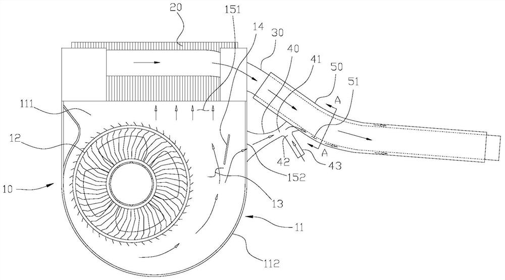
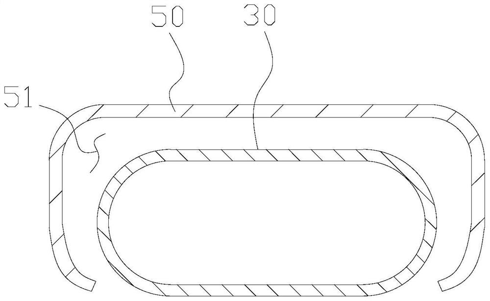
[0029] Such as figure 1 As shown, the embodiment of the present invention discloses a heat dissipation system, the heat dissipation system is installed in the shell of the system end of the notebook computer (a kind of electronic equipment), and the heat dissipation system includes: a heat dissipation fan 10, a heat dissipation fin 20 ( As a heat dissipation component) and heat pipe 30.

[0030] The heat dissipation fin 20 is arranged at the main air outlet 151 of the heat dissipation fan 10, the root of the heat conduction pipe 30 is connected to the heat dissipation fin 20, and the far end of the heat conduction pipe 30 stretches out of the shell, and the heat dissipation fin 20 is close to the functional parts ( Such as CPU),...


PUM


Abstract

The invention discloses a heat dissipation system of electronic equipment. The system comprises a fan, the fan comprises a shell and an impeller arranged in the shell, and the shell is internally provided with a strong wind area close to a main air outlet. A flow guide plate is arranged in the strong wind area, and an auxiliary air outlet is formed in a shell of the fan so that airflow passing through the strong wind area can flow out of the auxiliary air outlet under the guidance of the flow guide plate. The auxiliary air outlet is connected with an air guide pipe, and the air guide pipe is used for guiding airflow so as to cool a heating component. According to the heat dissipation system provided by the invention, the system end can be maintained in a temperature range in which a user feels comfortable.

Description

technical field [0001] The invention relates to the technical field of heat dissipation of electronic equipment, in particular to a heat dissipation system of electronic equipment. Background technique [0002] As the thickness of the notebook computer is getting thinner, the heat dissipation space in the system side of the notebook computer is getting smaller and smaller. The cooling fan in the system side can’t reduce the temperature of the shell of the system side to the user’s comfortable temperature only by blowing air to the cooling fins. For this reason, in the prior art, the cold airflow provided by the cooling fan is divided into two parts, one part of the airflow is blown outward to the heat dissipation fins, and the other part of the airflow is blown to the inside of the shell at the system end, thereby reducing the system to a certain extent. end-to-end temperature range. [0003] However, the above-mentioned manner in the prior art has the following defects: ...

Claims


Application Information

Patent Timeline
Patent Type & Authority Applications(China)
IPC IPC(8): G06F1/20H05K7/20
CPCG06F1/203H05K7/20136H05K7/20145
Inventor 蔡佩珊
Owner HEFEI LCFC INFORMATION TECH
Why Eureka
Try Eureka