Temperature measuring mechanism of ring main unit

A ring network cabinet and connection mechanism technology, which is applied in the field of ring network cabinets, can solve problems such as errors that are prone to occur, and achieve the effects of reducing losses, improving temperature measurement accuracy, and avoiding measurement failures

Pending Publication Date: 2022-02-18
深圳市载宇电气技术有限公司
View PDF0 Cites 0 Cited by
  • Summary
  • Abstract
  • Description
  • Claims
  • Application Information

AI Technical Summary

Problems solved by technology

[0004] The purpose of the present invention is to solve the problem that the temperature measuring probe is in the cabinet for a long time, which leads to error problems in the temperature measuring process, and the proposed ring network cabinet temperature measuring mechanism

Method used


Image

  • Temperature measuring mechanism of ring main unit
  • Temperature measuring mechanism of ring main unit
  • Temperature measuring mechanism of ring main unit

Examples


Embodiment 1

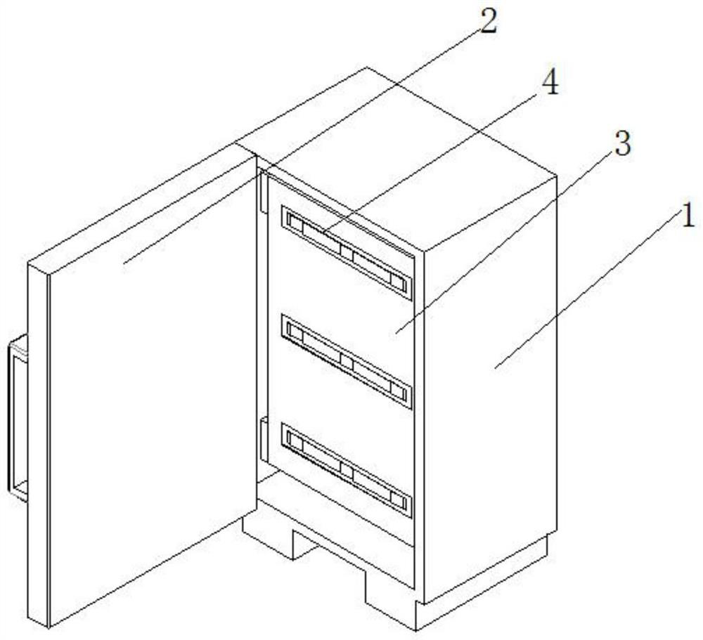
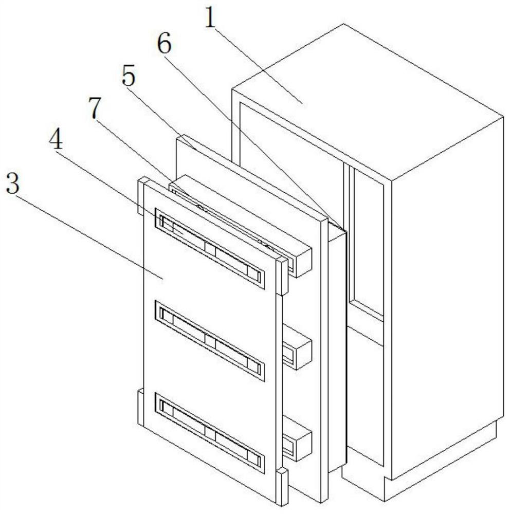
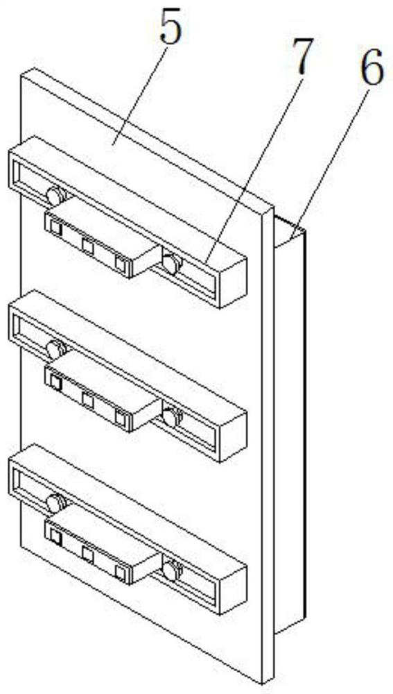
[0029] Embodiment 1, with reference to Figure 1-8 , the temperature measuring mechanism of the ring network cabinet, including the cabinet body 1, the outer wall of one side of the cabinet body 1 is movably connected with the cabinet door 2, the inner wall of the cabinet body 1 is fixedly connected with the installation plate 3, and the outer wall of one side of the installation plate 3 is provided with Rectangular slot, the inner wall of the rectangular slot is fixedly connected with the mounting seat 4, the inner wall of the cabinet body 1 is fixedly connected with the partition 5, and the outer wall of one side of the partition 5 is fixedly connected with the heat conduction mechanism 7, one end of the heat conduction mechanism 7 and the installation plate 3 In contact with each other, the outer wall on the other side of the partition 5 is fixedly connected with the detection box 6, the heat conduction mechanism 7 includes a heat conduction seat 8, the inner wall of the hea...

Embodiment 2

[0032] Embodiment 2, with reference to Figure 1-7 And 9, the temperature measuring mechanism of the ring network cabinet, including the cabinet body 1, the outer wall of one side of the cabinet body 1 is movably connected with the cabinet door 2, the inner wall of the cabinet body 1 is fixedly connected with the installation plate 3, and the outer wall of one side of the installation plate 3 is There is a rectangular slot, the inner wall of the rectangular slot is fixedly connected with the installation seat 4, the inner wall of the cabinet body 1 is fixedly connected with the partition 5, and the outer wall of one side of the partition 5 is fixedly connected with the heat conduction mechanism 7, one end of the heat conduction mechanism 7 and the installation The plates 3 are in contact with each other, and the outer wall on the other side of the partition 5 is fixedly connected with a detection box 6. The heat conduction mechanism 7 includes a heat conduction seat 8, and the ...


PUM


Abstract

A temperature measuring mechanism of a ring main unit is disclosed by the present invention, and comprises a cabinet body, the outer wall of one side of the cabinet body is movably connected with a cabinet door, the inner wall of the cabinet body is fixedly connected with a mounting plate, the outer wall of one side of the mounting plate is provided with a rectangular groove, the inner wall of the rectangular groove is fixedly connected with a mounting seat, the inner wall of the cabinet body is fixedly connected with a partition plate, the outer wall of one side of the partition plate is fixedly connected with a heat conduction mechanism, and one end of the heat conduction mechanism makes contact with the mounting plate. According to the invention, the heat conduction mechanism is arranged between the mounting plate and the partition plate, and a plurality of connecting mechanisms are arranged in the heat conduction mechanism, so that the temperature of different areas on the mounting plate can be conducted out; and a temperature measuring seat corresponding to the heat conduction mechanism is arranged in the detection box, and a temperature measurement probe in a detection mechanism in the detection box is matched to measure the temperature of the temperature measurement seat, so that the temperature of different areas on the mounting plate can be conveniently measured, and errors during measurement are reduced.

Description

technical field [0001] The invention relates to the technical field of ring network cabinets, in particular to a temperature measuring mechanism of a ring network cabinet. Background technique [0002] The ring network cabinet is a group of transmission and distribution electrical equipment (high-voltage switchgear) installed in a metal or non-metal insulated cabinet or made into an assembled interval ring network power supply unit. Its core part uses load switches and fuses. It has a structure Simple, small size, low price, can improve power supply parameters and performance, and power supply security and other advantages. It is widely used in distribution stations and box-type substations of load centers such as urban residential quarters, high-rise buildings, large public buildings, factories and enterprises. [0003] The existing ring network cabinet is directly tested through the temperature measuring probe in the cabinet when measuring the temperature, but because the...

Claims


Application Information

Patent Timeline
IPC IPC(8): H02B1/26G05D23/20
CPCH02B1/26G05D23/20
Inventor 徐天怿陶敏毅
Owner 深圳市载宇电气技术有限公司
Why Eureka
Try Eureka