
Direct-current power supply system

A DC power supply system, DC power supply technology, applied in the parallel operation of DC power supply, DC circuits with more than three wires, DC network circuit devices, etc. Maximize utilization, reduce labor costs, improve safety and reliability

Pending Publication Date: 2022-02-18
GUANGZHOU HONGHUAI ENERGY TECH CO LTD
View PDF0 Cites 0 Cited by
  • Summary
  • Abstract
  • Description
  • Claims
  • Application Information

AI Technical Summary

Problems solved by technology

The two sets of DC power supply equipment are connected through a bus tie switch, and when necessary, the knife switch is closed by manual operation for mutual backup. During the closing process, the two sets of batteries will be connected in parallel for a short time, causing the risk of circulation, and manual on-site operation is required , it is impossible to realize remote automatic operation and real-time backup. Some substations try to use electric control bus tie to realize remote control, but once the electric control switch fails, the direct parallel connection of two sets of batteries will increase the probability of the above risks

Method used


Image

  • Direct-current power supply system
  • Direct-current power supply system

Examples


Embodiment 1

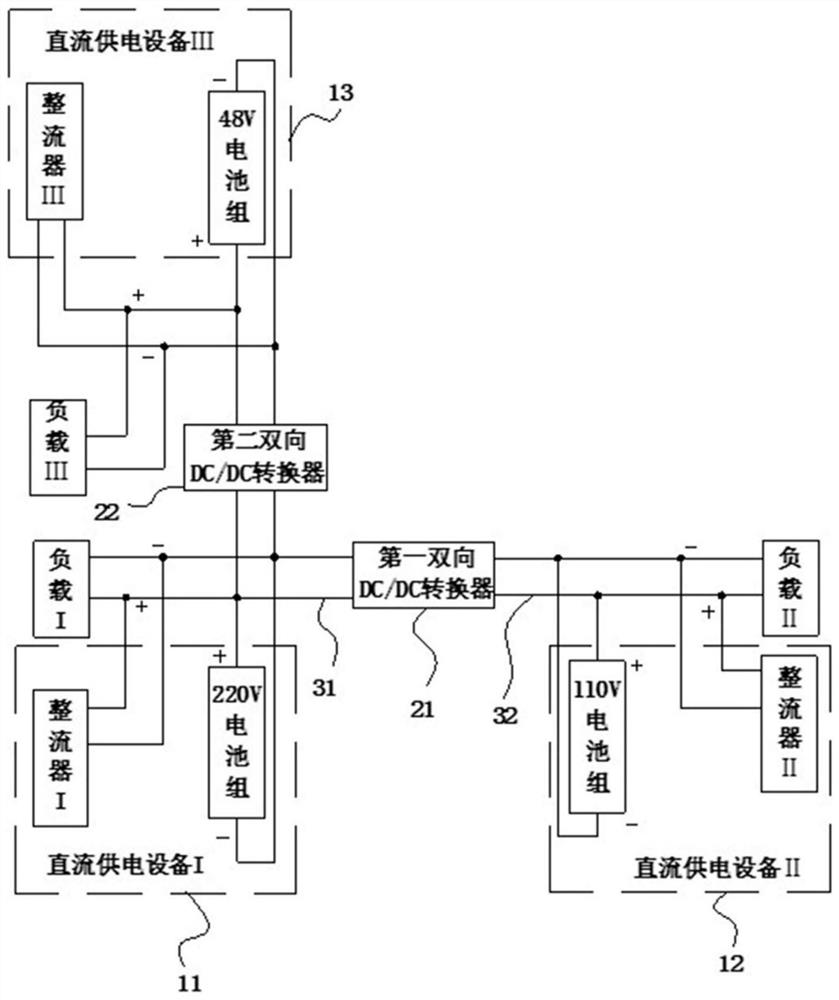
[0025] See figure 1 , a DC power supply system, which includes: DC power supply equipment I11, DC power supply equipment II12, DC power supply equipment III13, a first bidirectional DC / DC converter 21, a converter second bidirectional DC / DC converter 22, a first direct current A flow bus 31 , a second DC bus 32 and a controller (not shown).

[0026] The DC power supply device I11 is connected to one end of the first bidirectional DC / DC converter 21 of the converter through the first DC bus 31 . The DC power supply device I11 is a 220V DC power supply device, which includes a rectifier I and a 220V battery pack. Under normal circumstances, the rectifier I converts the mains power into direct current to supply power for the load I. When the mains power supply is abnormal , the load I is powered by a 220V battery pack.

[0027] The DC power supply device II12 is connected to the other end of the first bidirectional DC / DC converter 21 of the converter through the second DC bus b...

Embodiment 2

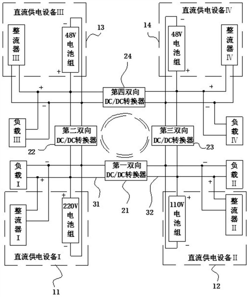
[0035] See figure 2 The difference between Embodiment 2 and Embodiment 1 is that in Embodiment 2, the DC power supply system is also provided with a third bidirectional DC / DC converter 23, a fourth bidirectional DC / DC converter 24, and DC power supply equipment IV 14 .

[0036] The third bidirectional DC / DC converter 23 is used to convert 48V DC to 110V DC and 110V DC to 48V DC; the fourth bidirectional DC / DC converter 24 is used to convert 48V DC to 48V DC and is bidirectional.

[0037] The DC power supply device IV14 is connected to the second DC bus 32 through the third bidirectional DC / DC converter 23 . The DC power supply device IV14 is a 48V DC power supply device, which includes a rectifier IV and a 48V battery pack, and one end of the fourth bidirectional DC / DC converter 24 is connected to the second bidirectional DC / DC converter;

[0038] The other end of the fourth bidirectional DC / DC converter 24 is connected to the third bidirectional DC / DC converter 23; the fir...


PUM


Abstract

The invention discloses a direct-current power supply system which comprises a direct-current power supply device I, a direct-current power supply device II, a direct-current power supply device III, a first bidirectional DC / DC converter, a second bidirectional DC / DC converter, a first direct-current bus and a second direct-current bus. According to the invention, a plurality of direct-current power supply devices are mutually physically isolated and do not interfere with each other; a circulating current risk caused by parallel connection does not occur at any time, and the safety and the reliability of a direct-current power supply system are greatly improved; a plurality of direct current power supply devices and the bidirectional DC / DC converter can form a plurality of power supply paths, so that a plurality of standby power supply paths are provided for a plurality of loads, direct and indirect cost losses caused by faults are reduced, and sharing and maximum utilization of the direct current power supply devices are realized; and according to the invention, remote control can be realized, so that the workload caused by manual on-site operation in the prior art is avoided, and the labor cost is further reduced.

Description

technical field [0001] The invention relates to the field of DC power supply equipment, in particular to a DC power supply system. Background technique [0002] The DC power supply equipment in the substation is a power supply equipment that can provide DC power to various equipment and can be operated independently. It can provide certain protection for switch control, emergency lighting, signal equipment, and system monitoring. It is usually not affected by the system. influence on the way it operates. If the external AC power of the system is suddenly interrupted, the battery can be used to supply power to the DC power supply equipment, so that the system can operate normally. Since the battery pack is connected in series, its performance and life are difficult to predict. If a single battery cell is open or fails, the entire battery pack will lose its backup capability. Once the battery pack fails or there is a circulating current between two DC power supply equipment ...

Claims


Application Information

Patent Timeline
Patent Type & Authority Applications(China)
IPC IPC(8): H02J1/10H02J1/08H02J9/06
CPCH02J1/10H02J1/082H02J1/086H02J9/061H02J9/068
Inventor 黄尚南康娟瞿琦赵俊祥
Owner GUANGZHOU HONGHUAI ENERGY TECH CO LTD
Learn More