
Capacitor control method and system

A control method and capacitor technology, applied in electrical components, circuit devices, AC network circuits, etc., can solve problems such as switching and oscillation of capacitors, and achieve the effects of prolonging service life, avoiding frequent trips, and avoiding contact sticking

Pending Publication Date: 2022-02-18
DELIXI GROUP INSTRUMENT CO LTD
View PDF0 Cites 0 Cited by
  • Summary
  • Abstract
  • Description
  • Claims
  • Application Information

AI Technical Summary

Problems solved by technology

[0005] Aiming at the deficiencies of the prior art, the present invention solves the problem of frequent switching and switching oscillations caused by protection of capacitors in the grid environment

Method used


Image

  • Capacitor control method and system
  • Capacitor control method and system

Examples


Embodiment 1

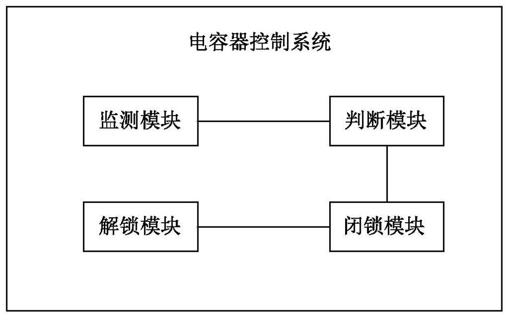
[0084] Embodiment 1 of the capacitor control system of the present invention includes:

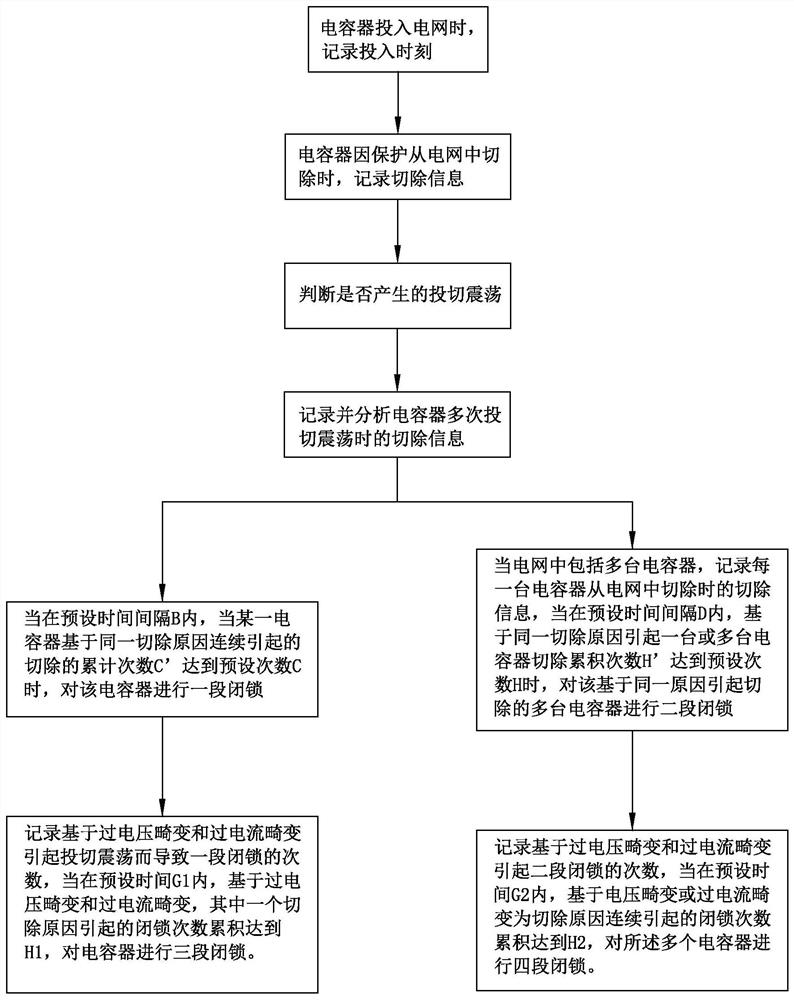
[0085] The monitoring module is used to monitor the time when the capacitor is put into the power grid, and the cut-off information when the capacitor is cut off from the power grid, the cut-off information includes the cut-off time and the reason for the cut-off;

[0086] A judging module, connected to the monitoring module, to obtain the input time and removal information, and calculate the difference between the capacitor input time and the removal time as the removal time difference. When the removal time difference is less than the preset time A, it is judged as switching Shock;

[0087] The blocking module is connected to the judging module, records and analyzes the removal information when the capacitor is switched and oscillated multiple times, when within the preset time interval B, when the cumulative number of times C' of the capacitor is continuously cut based on the same reaso...

Embodiment 2

[0118] Embodiment 2 of the capacitor control system of the present invention includes:

[0119] The monitoring module is used to monitor the time when each capacitor in the power grid is put into the power grid, and the cut-off information when it is cut off from the power grid. The cut-off information includes the cut-off time and the reason for the cut-off;

[0120] A judging module, connected to the monitoring module, to obtain the input time and removal information, and calculate the difference between the input time and the removal time of each capacitor as the removal time difference. When the removal time difference is less than the preset time A, judge For switching shock;

[0121] The blocking module is connected to the monitoring module to obtain the removal information of each capacitor when it is removed from the power grid. When within the preset time interval D, the cumulative number of times H' of multiple capacitor removals reaches the preset number based on th...


PUM


Abstract

The invention discloses a capacitor control method, and the method comprises the following steps: when a capacitor is put into a power grid, recording the putting moment; when the capacitor is cut off from the power grid due to protection, recording cut-off information; judging whether the oscillation is switching oscillation or not; when switching oscillation is carried out, carrying out one section of locking on the capacitor; or when the power grid comprises a plurality of capacitors, recording removal information when each capacitor is removed from the power grid; judging whether the oscillation is switching oscillation or not; and during switching oscillation, carrying out the two-section locking on the corresponding capacitor. In addition, the invention further discloses a capacitor control system which comprises a monitoring module, a judgment module and a locking module. According to the invention, frequent switching oscillation caused by influence of a power grid environment when the low-voltage reactive power compensation device works is effectively solved, latch-up protection is added, and the service life of the capacitor is prolonged.

Description

technical field [0001] The invention relates to the field of reactive power compensation, in particular to a capacitor control method and system. Background technique [0002] When the power system supplies power to nonlinear electrical equipment and loads in the power grid, these equipment and loads convert part of the fundamental energy into harmonic energy while transmitting, transforming, and absorbing the fundamental energy supplied by the system. A large amount of harmonic current is injected into the system, which seriously distorts the sinusoidal waveform of the power grid. These electrical equipment and electrical loads that generate harmonics are called harmonic sources. When a harmonic source excites a circuit whose inductive reactance and capacitive reactance are approximately equal at the harmonic frequency, the circuit will have harmonic resonance. The combination of the capacitor's harmonic capacitive reactance and the system's harmonic inductance will cause ...

Claims


Application Information

Patent Timeline
Patent Type & Authority Applications(China)
IPC IPC(8): H02J3/18H02J3/01
CPCH02J3/18H02J3/1892H02J3/01Y02E40/30Y02E40/40
Inventor 高亮亮黄万隆陶显升丁正光汤蓓蕾徐良浩
Owner DELIXI GROUP INSTRUMENT CO LTD
Learn More