Hot pot capable of realizing liquid level lifting
A hot pot and liquid level technology, which is applied to the structure of cooking utensils, inserts, cooking utensils and other directions, can solve the problems of high mold cost, installation requirements, and inability to achieve liquid level lifting, etc., to reduce dimensional accuracy requirements and reduce manufacturing costs. , the effect of improving the versatility
- Summary
- Abstract
- Description
- Claims
- Application Information
AI Technical Summary
Problems solved by technology
Method used
Image
Examples
Embodiment 1
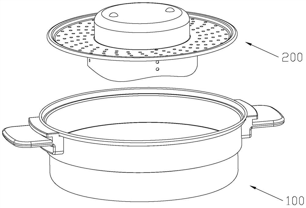
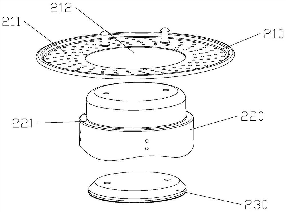
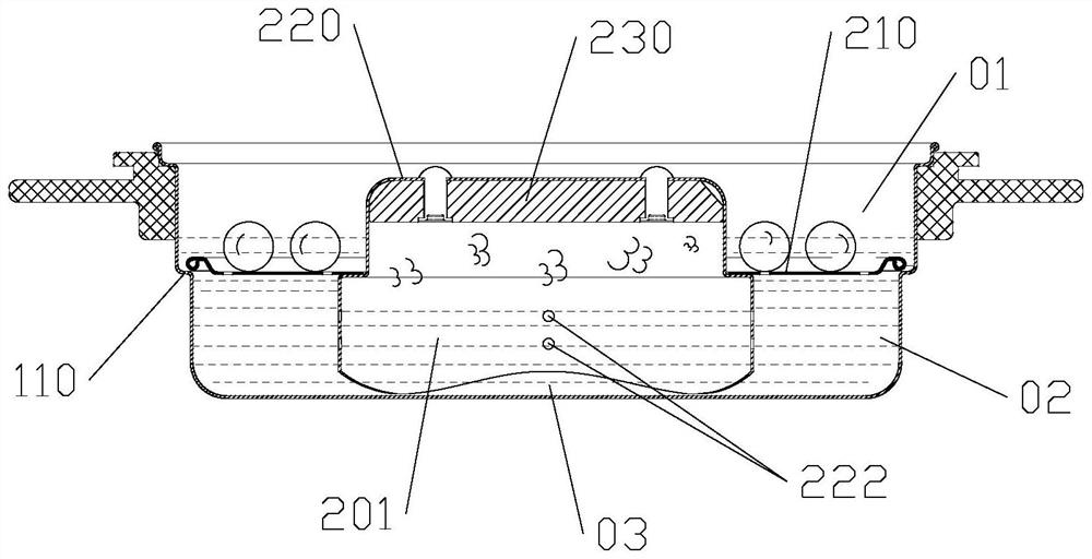
[0045] refer to Figure 1 to Figure 5 As shown, the hot pot in this embodiment includes a soup pot 100 and a material tray 200 placed in the soup pot 100. The material tray 200 divides the soup pot into an upper space 01 for accommodating ingredients and a lower space 02 for accommodating soup juice. There is a breathing chamber 201 with an open lower end. At least part of the breathing chamber 201 is located in the lower space 02 to accommodate part of the soup. The breathing chamber 201 communicates with the lower space 02. Hole 211.
[0046] Specifically, the tray 200 in this embodiment includes a bottom wall 210 and a breathing tube 220 connected to the bottom wall 210. The bottom wall 210 divides the soup pot into an upper space 01 for containing ingredients and a lower space 02 for containing soup. The breathing tube The lower end of the breathing tube 220 is open, the upper end of the breathing tube 220 is closed, and the breathing cavity 201 is formed inside the breat...
Embodiment 2
[0060] refer to Figure 6 As shown, compared with Embodiment 1, the difference of this embodiment is that the tray in this embodiment includes a bottom wall 210 and a breathing tube 220 with open upper and lower ends, and the bottom wall 210 includes a first bottom wall 213 and The second bottom wall 214 is arranged around the first bottom wall 213 , the liquid hole 211 is provided on the second bottom wall 214 , and the first bottom wall 213 is sealed with the top of the breathing tube to define and form the above-mentioned breathing chamber 201 .
[0061] Preferably, the first bottom wall 213 arches upwards to form an inverted cover body, the cover body and the second bottom wall 214 are integrally formed, and the cover body seals with the top of the breathing tube to define a breathing chamber, and the cover body can be welded The way is sealed with the top of the breathing tube, or a seal is provided between the cover body and the top of the breathing tube, and the cover b...
Embodiment 3
[0064] refer to Figure 7As shown, compared with the second embodiment, the difference of this embodiment is that, in order to make the upper space 01 accommodate more food materials, all the breathing chambers 201 can be located in the lower space 02. At this time, the first bottom wall 213 and The second bottom wall 214 is flat, and the first bottom wall 213 is sealed with the top of the breathing tube to define and form the above-mentioned breathing chamber 201. The first bottom wall 213 can be welded and sealed with the top of the breathing tube, or the second A seal is provided between the bottom wall 213 and the top of the breathing tube, and the first bottom wall 213 and the top of the breathing tube are fixed by screws; or the first bottom wall 213 and the breathing tube 220 are integrally formed.
[0065] In this solution, the counterweight 230 is fixed on the side wall of the breathing tube. At this time, the side wall of the breathing tube is provided with an inward...
PUM
 Abstract
Description
Claims
Application Information
 - R&D
- Intellectual Property
- Life Sciences
- Materials
- Tech Scout
- Unparalleled Data Quality
- Higher Quality Content
- 60% Fewer Hallucinations
Browse by: Latest US Patents, China's latest patents, Technical Efficacy Thesaurus, Application Domain, Technology Topic, Popular Technical Reports.
© 2025 PatSnap. All rights reserved.Legal|Privacy policy|Modern Slavery Act Transparency Statement|Sitemap|About US| Contact US: help@patsnap.com


