Up-and-down reciprocating type bicycle and rickshaw transmission mechanism
A technology of transmission mechanism and bicycle, applied in chain/belt transmission, vehicle parts, vehicle gearbox, etc., can solve the problem that it is difficult for ordinary people to ride long distances, affects the willingness of cyclists to ride, and tenderness of cyclists' hip muscles, etc. problems, to achieve the effect of simple and compact overall structure, increased riding comfort, and small front and rear movement distance
- Summary
- Abstract
- Description
- Claims
- Application Information
AI Technical Summary
Problems solved by technology
Method used
Image
Examples
specific Embodiment approach 1
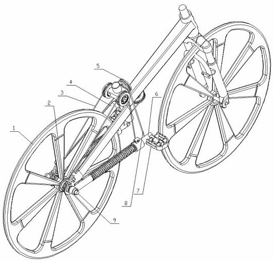
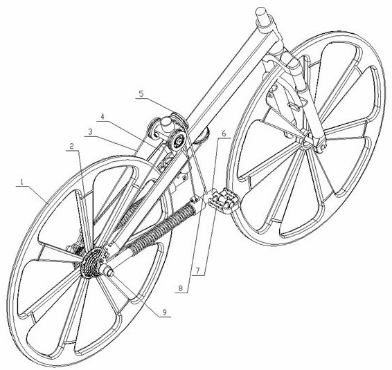
[0037] Specific implementation mode one: please refer to Figure 1-10 , the present invention provides a technical solution: an up and down reciprocating bicycle and rickshaw transmission mechanism, comprising: a flywheel 2, a vehicle frame 4 and a connecting rod 6;
[0038] The flywheels 2 are arranged in two groups, and the flywheels 2 include a ratchet mechanism, and the rear wheels 1 are mounted on the rear wheel shaft 9, while two groups of flywheels 2 are respectively installed on both sides of the rear wheels 1, and the two groups of flywheels 2 are respectively installed with Transmission structure 3;
[0039] Four sets of fixed pulleys 5 are installed in the middle of the vehicle frame 4, and a set of fixed pulleys 5 mounted on the front of the vertical column of the vehicle frame is sleeved with linkage ropes 8, while the other three sets of fixed pulleys 5 are sleeved with transmission structures 3, The two ends of the linkage rope 8 are respectively connected to t...
specific Embodiment approach 2
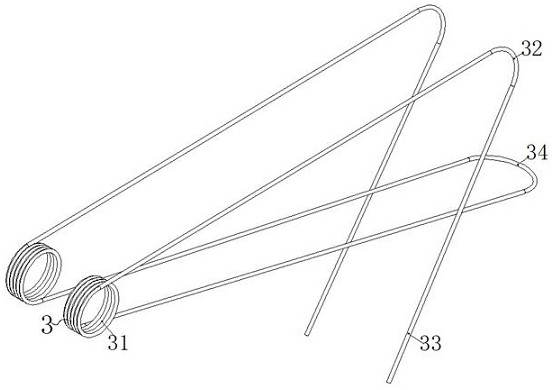
[0042] Embodiment 2: This embodiment is a further limitation of Embodiment 1. The transmission structure 3 is a transmission rope, and the transmission rope is a three-section type. The middle section of the transmission rope is an elastic rope, and the two sides of the elastic rope are inelastic ropes. , the transmission structure 3 includes a winding drive part 31, a pulley transmission part 32, a connection part 33 and an elastic tension end 34, and the winding drive part 31, the pulley transmission part 32 and the connection part 33 are all arranged in two groups, and the two groups of winding drive parts 31 are respectively installed on the flywheel 2 on both sides of the rear wheel 1, two sets of pulley transmission parts 32 are respectively installed on the fixed pulleys 5 on both sides of the top of the middle part of the vehicle frame 4, and the lower ends of the two sets of connecting parts 33 are respectively installed on the two sets of connecting pulleys. On the su...
specific Embodiment approach 3
[0046] Embodiment 3: This embodiment is a further limitation of Embodiment 2. The number of turns of the winding drive part 31 is at least two groups, and the winding drive part 31 is directly wound on the flywheel 2. At the same time, the rope located in the middle of the winding drive part 31 One point of the ring can be fixed on the flywheel 2.
[0047] The middle position point of the winding circle on the winding driving part 31 is fixed on the flywheel 2 as a non-essential condition, as the static friction force between the gearless flywheel 2 and the rope is enough for transmission and can not be fixed, and then it is bypassed and installed in the middle of the vehicle frame 4 The fixed pulley 5 reaches the other side of the frame 4, winds the toothless flywheel 2 on the opposite side for several turns, and then bypasses the fixed pulley 5 mounted on the opposite side of the frame 4, and finally adjusts with the connecting rod 6 on the opposite side. The block 61 is con...
PUM
 Abstract
Description
Claims
Application Information
 - R&D
- Intellectual Property
- Life Sciences
- Materials
- Tech Scout
- Unparalleled Data Quality
- Higher Quality Content
- 60% Fewer Hallucinations
Browse by: Latest US Patents, China's latest patents, Technical Efficacy Thesaurus, Application Domain, Technology Topic, Popular Technical Reports.
© 2025 PatSnap. All rights reserved.Legal|Privacy policy|Modern Slavery Act Transparency Statement|Sitemap|About US| Contact US: help@patsnap.com


