Supercharge Your Innovation With Domain-Expert AI Agents!

Underwater bionic propeller and movement method thereof

A propeller and thruster technology, which is applied in the field of underwater bionic propellers and its motion, can solve the problems of inability to change the route path conveniently, cannot achieve convenience, etc., and achieves the convenience of changing the navigation direction, simple and convenient operation, and high sensitivity Effect

Pending Publication Date: 2022-02-25
JIANGSU UNIV OF SCI & TECH
View PDF1 Cites 0 Cited by
  • Summary
  • Abstract
  • Description
  • Claims
  • Application Information

AI Technical Summary

Problems solved by technology

[0002] By studying the movement principle of fish, the bionic underwater propeller is designed. The use of the propeller improves the convenience of underwater operations, making users more labor-saving when diving, and also reduces the fatigue caused by underwater operations. However, in the actual use of various underwater bionic propellers today, the user can only rely on the user to swing the overall direction of the device to change the route path, which cannot achieve the purpose of convenience
[0003] For example, CN104816808B is a bionic undulating long-fin underwater propeller, each fin ray is driven independently by connecting a first steering gear through a first bevel gear and a second bevel gear, and the surface of the long fin is made of a flexible film of latex material. Driven by the fins, it can realize a variety of sinusoidal or other types of waveforms and interact with water to generate stable propulsion, but it cannot easily change the route path

Method used


Image

  • Underwater bionic propeller and movement method thereof
  • Underwater bionic propeller and movement method thereof
  • Underwater bionic propeller and movement method thereof

Examples


Embodiment Construction

[0024] The present invention will be further illustrated below in conjunction with the accompanying drawings and specific embodiments, and it should be understood that these embodiments are only for illustrating the present invention and are not intended to limit the scope of the present invention.

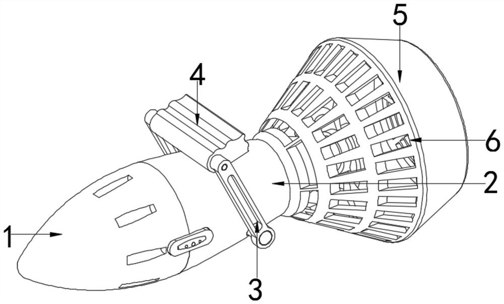
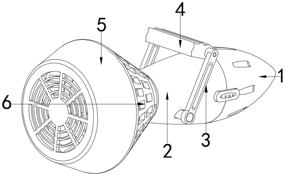
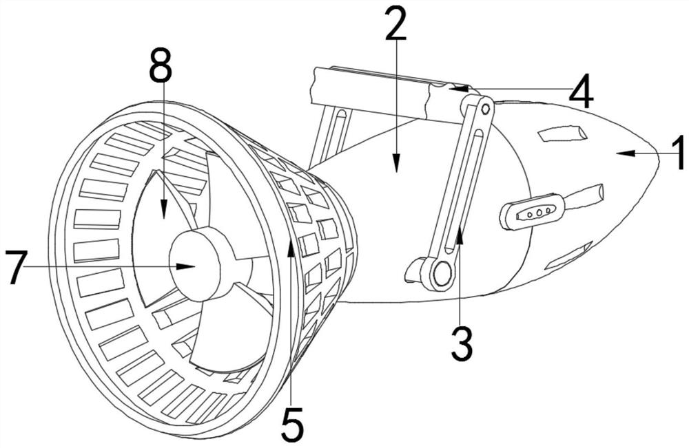
[0025] An underwater bionic propeller, such as Figure 1~6 As shown, it includes a push head 1, a casing 2, a swing rod 3, a hand plate 4, a protection box 5, a blade assembly, and a direction changing mechanism.

[0026] The push head 1 is bullet-shaped, the flat end of the push head 1 is fixed to one end of the casing 2, and the direction changing mechanism is connected to the other end of the casing 2. The direction changing mechanism includes a connecting column 9, a limit plate 12, a push rod 13, and a soft rod 14 , transmission parts, pushing components, the interior of the connecting column 9 is provided with a cavity, one end of which is fixed to the shell 2, and a convex ...


PUM


Abstract

The invention discloses an underwater bionic propeller which comprises a propeller head, a shell, a protection box, a blade assembly and a turning mechanism, the flat end of the propeller head is fixed to one end of the shell, the turning mechanism is connected with the other end of the shell, one end of the protection box is arranged on the shell in a sleeving mode and fixed to the peripheral face of the protection box, and the turning mechanism is located in the protection box; the blade assembly is arranged in the protection box and rotationally connected with the turning mechanism, and a plurality of water flowing holes are distributed in the peripheral face of the protection box. A push rod is pressed to drive a soft rod to move, and the soft rod moves to initially extrude a top end arc plate to rotate, so that a right lapping plate is driven to move under the limitation of a chuck, the compressive resistance of the propeller is changed, the propeller shifts on the left side, and a left lapping plate moves, the compressive resistance of the propeller is changed, and the propeller shifts on the right side, so that the underwater operation is realized. And meanwhile, local parts are pulled, so that the propeller is subjected to different resistances underwater, and along with continuous movement of the propeller, the whole route shifts.

Description

technical field [0001] The invention relates to the technical field of bionic equipment, in particular to an underwater bionic propeller and a motion method thereof. Background technique [0002] By studying the movement principle of fish, the bionic underwater propeller is designed. The use of the propeller improves the convenience of underwater operations, making users more labor-saving when diving, and also reduces the fatigue caused by underwater operations. However, in the actual use of various underwater bionic propellers today, the user can only rely on the user to swing the overall direction of the device to change the route path, which cannot achieve the purpose of convenience. [0003] For example, CN104816808B is a bionic undulating long-fin underwater propeller, each fin ray is driven independently by connecting a first steering gear through a first bevel gear and a second bevel gear, and the surface of the long fin is made of a flexible film of latex material. ...

Claims


Application Information

Patent Timeline
IPC IPC(8): B63H1/36
CPCB63H1/36
Inventor 邵佳伟刘芳华王政狄澄吴万毅孙天圣缪游
Owner JIANGSU UNIV OF SCI & TECH
Features
  • R&D
  • Intellectual Property
  • Life Sciences
  • Materials
  • Tech Scout
  • Unparalleled Data Quality
  • Higher Quality Content
  • 60% Fewer Hallucinations
Learn More