
Device and method for carrying out diaphragm wall construction by utilizing slot milling machine under low clearance

A ground-to-wall, low-headroom technology, applied in mechanically driven excavators/dredgers, excavation, sheet pile walls, etc., can solve the problems of increasing construction risks, inability to use rotary drilling rigs, and low trough-forming efficiency, achieving savings The effect of construction procedures and costs, saving equipment maintenance costs, and improving slotting efficiency

Active Publication Date: 2022-02-25
BCEG CIVIL ENG +1
View PDF6 Cites 0 Cited by
  • Summary
  • Abstract
  • Description
  • Claims
  • Application Information

AI Technical Summary

Problems solved by technology

[0003] The prior art employs a construction process in which the rotary drilling rig and the percussion drilling rig alternately form slots, which has the disadvantages of cumbersome process, frequent process changes, and low slotting efficiency. Faults such as stuck hammer and dropped drill
If the operation is not done properly, it may even damage the groove wall of the ground connection wall, increasing the construction risk
At the same time, some terrain restrictions make it impossible to use equipment such as rotary drilling rigs and impact drilling rigs for construction.
[0004] The existing equipment for slot milling construction from the ground has no environmental restrictions, and the equipment adopts a high vertical structure, so it has the limitations of being too large and requiring a high clear height, and due to equipment functions and other structural limitations, It also cannot effectively achieve miniaturization, so it cannot support low headroom construction

Method used


Image

  • Device and method for carrying out diaphragm wall construction by utilizing slot milling machine under low clearance
  • Device and method for carrying out diaphragm wall construction by utilizing slot milling machine under low clearance
  • Device and method for carrying out diaphragm wall construction by utilizing slot milling machine under low clearance

Examples


Embodiment Construction

[0040] The following will clearly and completely describe the technical solutions in the embodiments of the present invention in conjunction with the accompanying drawings. Obviously, the described embodiments are only some of the embodiments of the present invention, not all of them. Based on the embodiments of the present invention, all other embodiments obtained by persons of ordinary skill in the art without making creative efforts belong to the protection scope of the present invention.

[0041] In the description of this patent, it is to be understood that the terms "center", "upper", "lower", "front", "rear", "left", "right", "vertical", "horizontal", The orientation or positional relationship indicated by "top", "bottom", "inner", "outer", etc. is based on the orientation or positional relationship shown in the drawings, and is only for the convenience of describing this patent and simplifying the description, rather than indicating or implying References to devices or...


PUM


Abstract

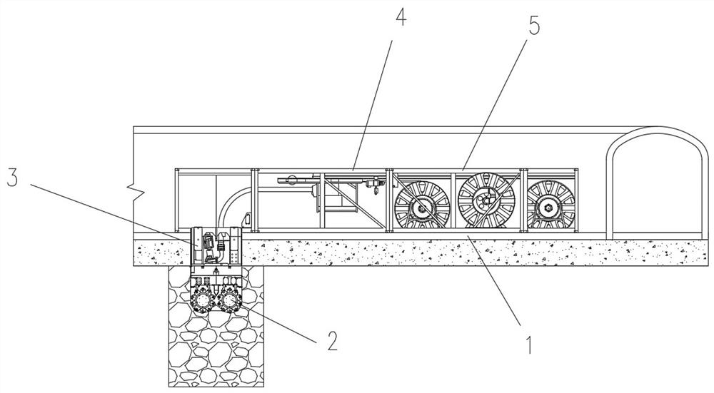
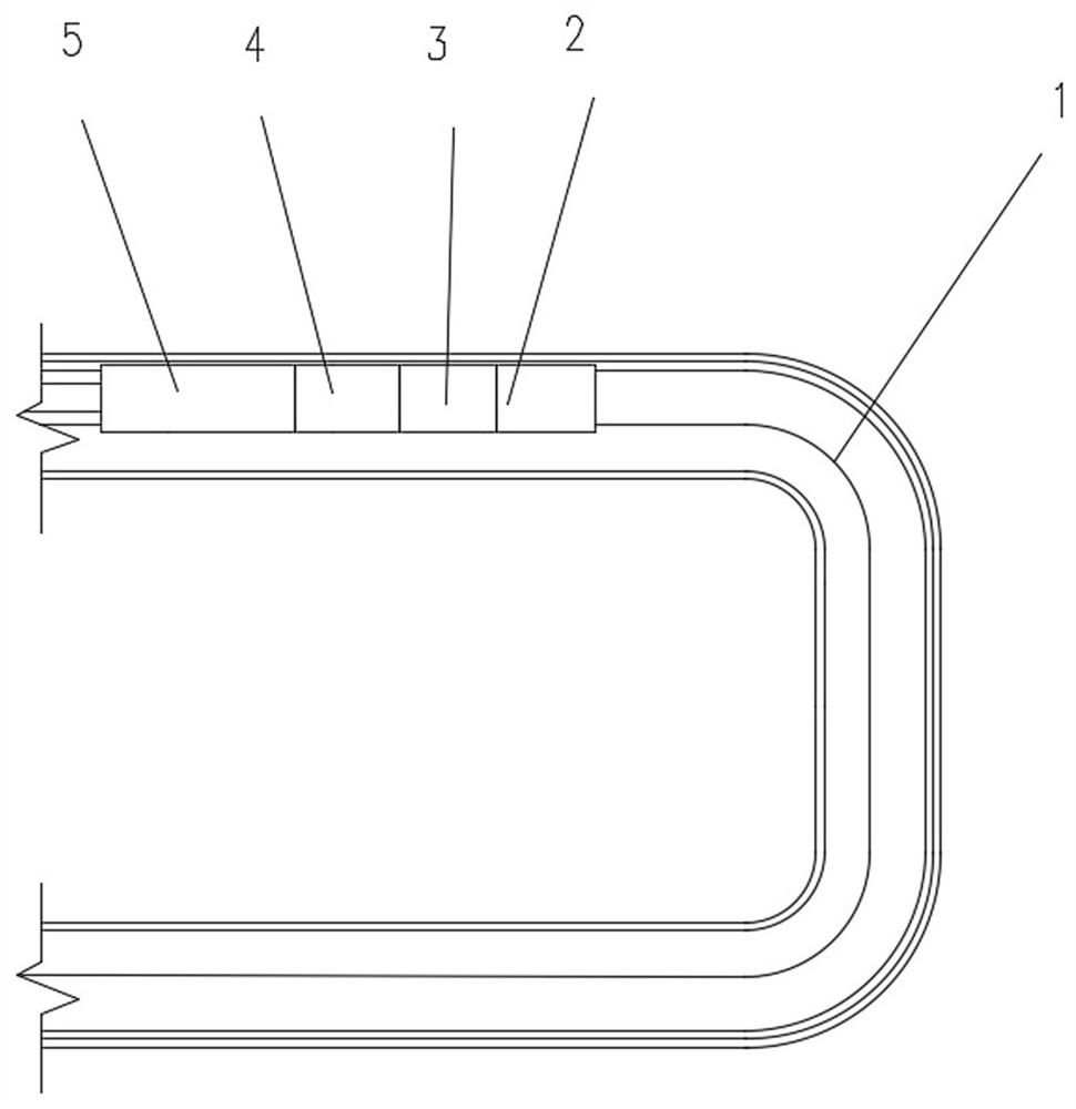
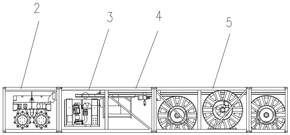
The invention discloses a device and method for carrying out diaphragm wall construction by utilizing a slot milling machine under low clearance, the device comprises a rail and a construction module, the rail is laid in a pilot tunnel, and the construction module comprises a milling module, a slurry pumping module, a rolling and hoisting module and an accessory reel module; the milling module, the slurry pumping module, the roll hoisting module and the accessory reel module are sequentially connected with one another from front to back and are all arranged on the track, and the slurry pumping module is connected with the milling module and the accessory reel module. Grooving equipment is miniaturized and modularized, the low-clearance construction condition is met, diaphragm wall construction at low clearance is achieved, the defect that large equipment cannot work under the specific terrain is overcome, meanwhile, the device has advantages that installation is convenient and fast, and the grooving effect is high are achieved, the defect that working procedures are frequently switched during large equipment construction can be effectively overcome, and the construction efficiency is improved.

Description

technical field [0001] The invention relates to the technical field of underground construction, in particular to a device and method for ground connection wall construction using a slot milling machine under low headroom. Background technique [0002] In the prior art, when constructing grooves in the underground ground wall, a rotary drilling rig is often used to form a plurality of rotary drilling holes in the groove section of the ground wall, and then an impact drill is used to hammer and hammer adjacent holes one by one from one end of the groove section to the other end. The partition wall between the two rotary drilling holes until a complete slot is formed; then the rotary drilling machine is converted into a clearing drill bit, and the rotary drilling machine is moved on the track, and the hoist is used to drive the clearing drill bit in the slot to punch up and down and move milling The small wall in the tank is left, and the sediment and pebbles in the tank are s...

Claims


Application Information

Patent Timeline
Patent Type & Authority Applications(China)
IPC IPC(8): E02F5/08E02F5/14E02F3/18E02F3/22E02F3/24E02D5/18E02D17/08
CPCE02F5/08E02F5/14E02F3/18E02F3/188E02F3/22E02F3/24E02F3/243E02D5/18E02D17/08
Inventor 孙希波陈建伟李峻峰王浩戴理张东贺尚修王伟孔令强毛鹏轩刘达吴楠戴宇
Owner BCEG CIVIL ENG
Learn More