Wire passing structure between instrument in oil pipe and oil sleeve annulus

An oil-casing annulus and instrument technology, which is applied in the direction of drill pipe, casing, drilling equipment, etc., can solve the problems of difficult crossing, tight radial space, and increased instrument cost, so as to facilitate on-site construction operations and simplify the structure , the effect of shortening the length of the structure

Pending Publication Date: 2022-02-25
贵州航天凯山石油仪器有限公司
View PDF0 Cites 0 Cited by
  • Summary
  • Abstract
  • Description
  • Claims
  • Application Information

AI Technical Summary

Problems solved by technology

[0003] 1. The plan of the crossing pipe, that is, the instrument is connected with the steel pipe cable in the oil pipe, and the steel pipe cable is led to the oil jacket annulus by means of the crossing joint; the length of the crossing pipe and other parts used in this method is relatively long, which increases the cost of the instrument, the overall length, It is inconvenient to go into the well on site, especially when the diameter of the steel pipe cable is thicker, the crossing is more difficult; in addition, the crossing joint involves the sealing of the steel pipe cable, and its technical reliability has a great impact on key processes such as subsequent expansion packers, which has certain risks ;
[0004] 2. The free edge structure scheme, that is, after the main body of the instrument and the connecting pipe are connected by a directional structure (boss, pin, etc.), the upper and lower threads are connected by the free edge nut to bear the load; this method uses the inner and outer shell structures, The relatively limited radial space is more tense, and the wall thickness of connecting structural parts such as union nuts is relatively thin, which is not suitable for long-term load bearing and pipe string impact in the downhole

Method used


Image

  • Wire passing structure between instrument in oil pipe and oil sleeve annulus
  • Wire passing structure between instrument in oil pipe and oil sleeve annulus
  • Wire passing structure between instrument in oil pipe and oil sleeve annulus

Examples


Embodiment Construction

[0026] The present invention will be further described in detail below in conjunction with the accompanying drawings and embodiments.

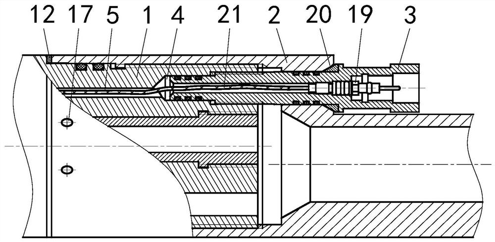
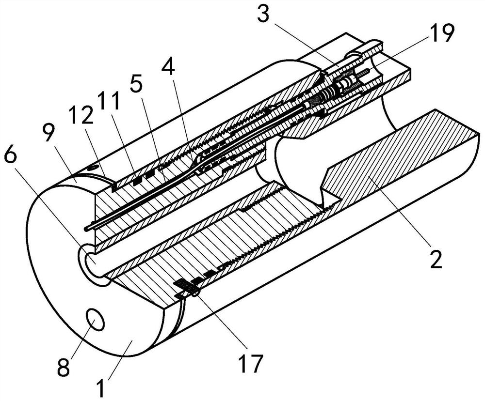
[0027] A line-passing structure between the instrument in the oil pipe and the annular space of the oil jacket of the present invention, such as figure 1 with figure 2 As shown, the wire-passing structure includes a body 1 and a lower connecting pipe 2; the body 1 and the lower connecting pipe 2 are connected in a dual manner by threads and pins 17; the body 1 is provided with a wire-passing installation hole 4; The hole 4 communicates with the bus through hole 5; the wire pipe 3 is installed in the wire pipe installation hole 4.

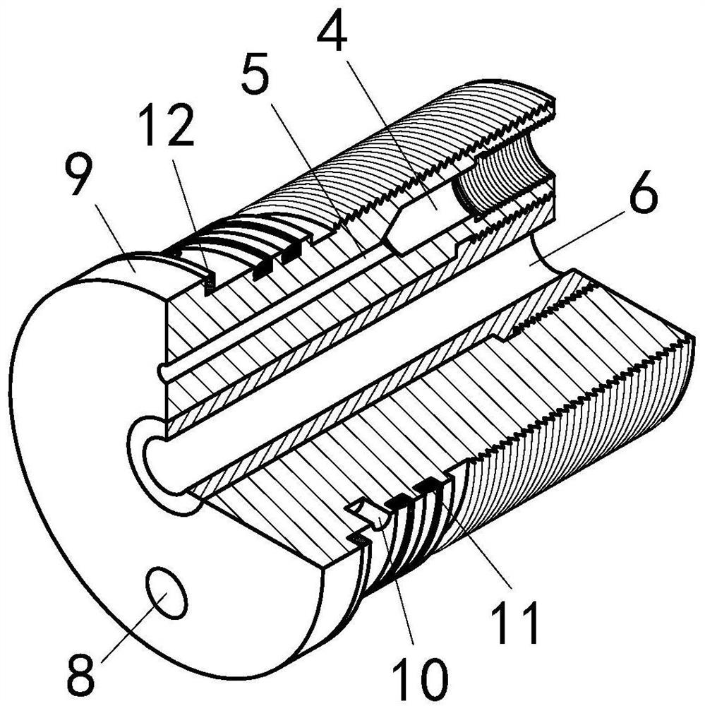
[0028] Such as image 3 As shown, the main body 1 is a cylindrical structure; the middle of the main body 1 is provided with a water inlet / oil outlet hole 6; The other side of the oil hole 6 is provided with an overflow channel 8; one side of the outer circle of the body 1 is provided with a boss 9; A group of ...


PUM


Abstract

The invention discloses a wire passing structure between an instrument in an oil pipe and an oil sleeve annulus. The wire passing structure comprises a body (1) and a lower connecting pipe (2). The body (1) and the lower connecting pipe (2) are connected in a double mode of threads and a pin (17). A wire passing pipe mounting hole (4) is formed in the body (1). The wire passing pipe mounting hole (4) communicates with the bus through hole (5). A wire passing pipe (3) is mounted in the wire passing pipe mounting hole (4). The method that the wire passing pipe penetrates through the eccentric holes in the body and the lower connecting pipe at the same time is adopted, simple and rapid wire passing between an instrument in an oil pipe and an oil sleeve annulus is achieved, the structural form of the position is greatly simplified, the structural length of the penetrating part is shortened, and site construction operation is facilitated; and the wire passing pipe plays a role in preventing rotation, and the pin further prevents rotation and reinforces the wire passing pipe.

Description

technical field [0001] The invention relates to a line-passing structure between an instrument in an oil pipe and an annular space of an oil casing, and belongs to the technical field of downhole instrument line-passing or pressure guiding. Background technique [0002] In the cabled separate production and injection process in oilfields, steel pipe cables (or armored wire cables) need to travel between the oil jacket annulus of oil and water wells and the inside of the oil pipe multiple times to provide power and communication for downhole equipment. Every crossing will involve issues such as sealing inside and outside the oil pipe and protection of cables. The above-mentioned problems are usually solved by using methods such as crossing tubes and free-edge structures, but generally have the following disadvantages: [0003] 1. The plan of the crossing pipe, that is, the instrument is connected with the steel pipe cable in the oil pipe, and the steel pipe cable is led to t...

Claims


Application Information

Patent Timeline
IPC IPC(8): E21B17/02E21B17/00H02G3/04H02G3/22
CPCE21B17/026E21B17/00E21B17/02H02G3/0418H02G3/0481H02G3/22
Inventor 王守舵张小波
Owner 贵州航天凯山石油仪器有限公司
Why Eureka
Try Eureka