Connector structure for ventilation pipe of crankcase of wind driven generator

A crankcase ventilation and wind turbine technology, which is applied to wind turbines, wind energy power generation, pipes/pipe joints/pipes and other directions, can solve problems such as unfavorable wind turbine energy collection, unsatisfactory crankcase heat dissipation, and increased energy consumption, etc. Achieve the effect of solving poor heat dissipation, reducing energy consumption and improving stability

Pending Publication Date: 2022-02-25
JIAXING MASTER PLUMBING
View PDF0 Cites 0 Cited by
  • Summary
  • Abstract
  • Description
  • Claims
  • Application Information

AI Technical Summary

Problems solved by technology

During the working process, the crankcase cover body needs to bear the high-speed rotating workload, which generates a lot of heat, which causes the working parts to heat up and affects the performance of the whole machine. It needs to meet sufficient heat dissipation conditions to ensure the normal operation of the whole machine. In the prior art, the hot air in the crankcase is generally communicated with the crankcase through the distribution pipe, so that the hot air in the crankcase is passed into the ventilation pipe, and then the ventilation pipe transports the hot air to the heat dissipation assembly, and the heat dissipation assembly cools down the hot air in the ventilation pipe. The final hot air will pass into the crankcase through another ventilation pipe, so that the cold air can cool down the crankcase. However, since the ventilation pipe and the heat dissipation component are connected to form a closed cycle, when the hot air is discharged, it may cause Backflow causes unsatisfactory heat dissipation in the crankcase. If a pump is added, energy consumption will increase, which is not conducive to better energy collection by wind turbines

Method used


Image

  • Connector structure for ventilation pipe of crankcase of wind driven generator
  • Connector structure for ventilation pipe of crankcase of wind driven generator
  • Connector structure for ventilation pipe of crankcase of wind driven generator

Examples


no. 1 example

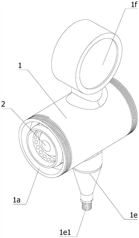
[0045] In the first embodiment, when the slider 2 provided by the present application allows hot air to enter the joint body 1 through the first groove 2d, it is convenient to concentrate the hot air inside the first groove 2d, so that the hot air can be better pushed The slider 2 moves; the hot air is concentrated and discharged into the interior of the joint body 1 through several first air outlets 2d1 on the side wall of the connecting part 2a, so that the slider 2 can be displaced for a small distance to make the hot air Flowing into the joint body 1, when the pressure of the hot air in the crankcase is low, the hot air can also be discharged in time to facilitate the circulation of the hot air, reduce the heat in the crankcase, prolong the service life of the equipment, and solve the above problems.

[0046] Further, the slider 2 provided by the present application still has the defect of lack of stability when sliding, and at the same time, in the case of insufficient hot...

no. 2 example

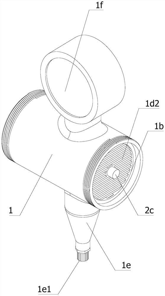
[0048] In the second embodiment, the slider 2 provided by this application allows hot air to enter the joint body 1 through the second groove 2e, so that the hot air is concentrated in the second groove 2e, so that the hot air can better push the slider. Block 2 moves; the hot air is discharged into between the inner wall of the joint body 1 and the outer wall of the connecting portion 2a through several second air outlets 2e1 on the side wall of the connecting portion 2a, and then passes through the third air outlet 2e2 of the limiting portion 2b. The hot air is discharged into the interior of the joint body 1. Since the diameter of the outer wall of the stopper 2b matches the diameter of the inner wall of the joint body 1, the slider 2 moves in close contact with the inner wall of the joint body 1, and is prevented by the third air outlet 2e2. It solves the problem that the hot air cannot circulate due to the joint between the slider 2 and the inner wall of the joint body 1, ...


PUM


Abstract

The invention relates to the technical field of generator equipment, in particular to a connector structure for a ventilation pipe of a crankcase of a wind driven generator, which comprises a connector body, a slider, a limiting rod, a limiting plate, a spring, a limiting block and a support frame, the slider is divided into a limiting part and a connecting part, a connecting hole is formed in the center of the support frame, and the limiting block and the support frame are positioned at two ends of the slider. One end of the limiting rod is sleeved with the connecting hole, the other end of the limiting rod is fixedly connected with the sliding block, the limiting plate is located on the limiting rod, the spring is located between the supporting frame and the limiting plate, the spring pushes the limiting plate to move towards a first opening, the limiting rod pushes the sliding block to move towards the first opening, and the limiting part abuts against the limiting block; hot air cannot flow back into a crankcase, the heat dissipation effect of the crankcase is ensured, the service life of equipment is prolonged, through the design, hot air extraction of a wind driven generator and other equipment can be reduced, energy consumption of the wind driven generator is reduced, and the wind driven generator can better collect energy.

Description

technical field [0001] The invention relates to the technical field of generator equipment, in particular to a joint structure for a crankcase ventilation pipe of a wind power generator. Background technique [0002] The crankcase cover is an important part of the assembled frequency conversion generator set. It is the installation base of some important parts in the whole generator set. For example, the rotating parts such as camshaft and crankshaft need to be installed on the crankcase cover. During the working process, the crankcase cover body needs to bear the high-speed rotating workload, which generates a lot of heat, which causes the working parts to heat up and affects the performance of the whole machine. It needs to meet sufficient heat dissipation conditions to ensure the normal operation of the whole machine. In the prior art, the hot air in the crankcase is generally communicated with the crankcase through the distribution pipe, so that the hot air in the crankc...

Claims


Application Information

Patent Timeline
IPC IPC(8): F16L29/00F16L41/03F16K15/06F16T1/38F03D80/60B01D46/10
CPCF16L29/00F16L41/03F16L41/008F16L41/021F16K15/063F16T1/38F16T1/386F03D80/60B01D46/10Y02E10/72
Inventor 陶忠明陶凯黄小芳周中皓高超
Owner JIAXING MASTER PLUMBING
Why Eureka
Try Eureka