
Air conditioner

A technology for air conditioners and empty cabinets, applied in air conditioning systems, space heating and ventilation, space heating and ventilation details, etc., can solve the problems of small utilization of heat exchange area, large internal space, impact, etc., to improve the structure Space utilization and the effect of increasing the heat exchange area

Pending Publication Date: 2022-02-25
GREE ELECTRIC APPLIANCES INC
View PDF0 Cites 0 Cited by
  • Summary
  • Abstract
  • Description
  • Claims
  • Application Information

AI Technical Summary

Problems solved by technology

Since the evaporator is placed obliquely in the form of a straight plate, the evaporator needs to occupy a large internal space of the hollow cabinet, which in turn increases the overall size of the cabinet air conditioner, and, in order to ensure the tilt support for the evaporator, It is necessary to install a supporting frame in the middle of the evaporator, which is in contact with the hollow cabinet and the evaporator, and the supporting frame is located in the direction where the cold air blows out toward the air outlet, which reduces the utilization rate of the heat exchange area of ​​the evaporator; In the process of the evaporator blowing air to the upper part, the utilization rate of the heat exchange area in the upper part of the evaporator is larger, and the heat exchange efficiency is higher, but the utilization rate of the heat exchange area in the lower part of the evaporator is small, and the heat exchange efficiency is lower, thereby reducing the The overall heat exchange efficiency of the evaporator, and because the cold air stroke is longer, that is, the cold air section is longer, it is easy to generate backflow inside the hollow cabinet, which not only has an adverse effect on the cooling effect, but also because the hot and cold air will flow on the display, The contact at the air outlet panel makes it easy to generate condensation on the display and the air outlet panel, which brings bad experiences to users such as affecting the display content of the display, condensation dripping indoors, etc.

Method used


Image

  • Air conditioner
  • Air conditioner
  • Air conditioner

Examples


Embodiment Construction

[0025] It should be noted that, in the case of no conflict, the embodiments in the present application and the features in the embodiments can be combined with each other. The present invention will be described in detail below with reference to the accompanying drawings and examples.

[0026] It should be pointed out that the following detailed description is exemplary and intended to provide further explanation to the present application. Unless defined otherwise, all technical and scientific terms used herein have the same meaning as commonly understood by one of ordinary skill in the art to which this application belongs.

[0027] The following will clearly and completely describe the technical solutions in the embodiments of the present invention with reference to the accompanying drawings in the embodiments of the present invention. Obviously, the described embodiments are only some, not all, embodiments of the present invention. The following description of at least on...


PUM


Abstract

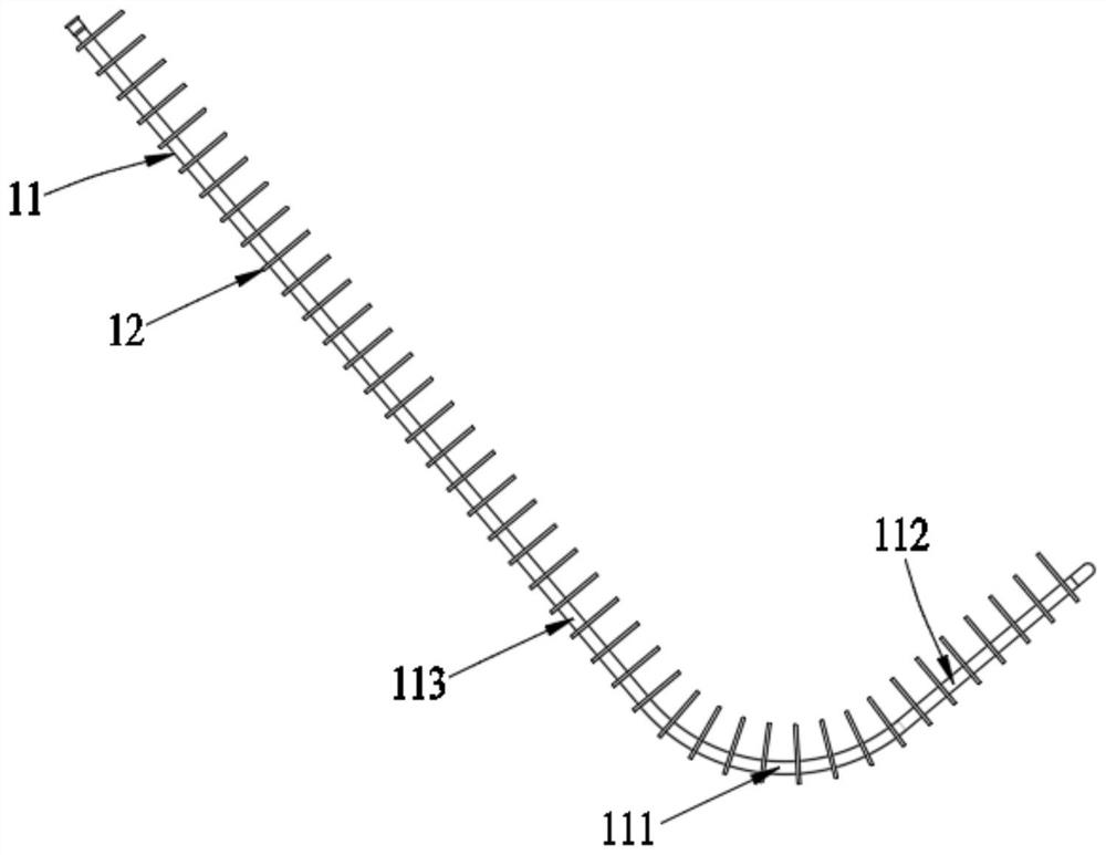
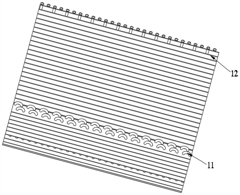
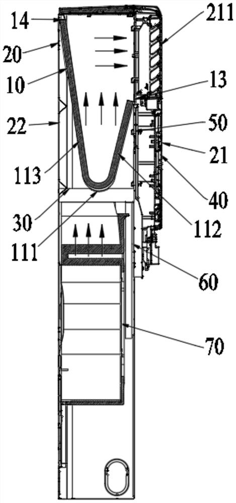
The invention belongs to the technical field of air conditioning, and particularly discloses an air conditioner which comprises a hollow cabinet body and a plate type indoor heat exchanger arranged in the hollow cabinet body, and a heat exchange main body of the plate type indoor heat exchanger comprises a plurality of heat exchange pipes arranged in parallel; the plurality of heat exchange tubes are arranged between the left cabinet plate and the right cabinet plate, and two ends of each heat exchange tube are respectively connected to the front cabinet plate and the rear cabinet plate; each heat exchange tube is provided with a bent part, and a first heat exchange part and a second heat exchange part which extend reversely from the two ends of the bent part and are connected to the front cabinet plate and the rear cabinet plate respectively; the first heat exchange part, the bent part and the second heat exchange part enable the heat exchange main body to form a windward heat exchange surface protruding towards the lower part of the hollow cabinet body; and the length of the first heat exchange part is smaller than that of the second heat exchange part, and the position, connected to the front cabinet plate, of the first heat exchange part is lower than the position, connected to the rear cabinet plate, of the second heat exchange part. The air conditioner has the advantages that the heat exchange efficiency is high, the refrigeration efficiency is high, the overall size can be reduced, and the condensation phenomenon is reduced or even eradicated.

Description

technical field [0001] The invention relates to the technical field of air conditioning, in particular to an air conditioner. Background technique [0002] At present, air conditioners such as cabinet air conditioners generally use a straight plate parallel flow evaporator included in the indoor heat exchanger to be placed obliquely on the upper part of the hollow cabinet, and centrifugal fan blades are arranged on the lower part of the hollow cabinet. The fins of the evaporator extend vertically from the upper part to the lower part of the hollow cabinet, and a water receiving pan is set at the position vertically below the fins, and the condensed water flows into the water receiving pan along the fins of the evaporator, and then passes through the drain pipe row away. When the existing cabinet type air conditioner is in cooling operation, the centrifugal fan blades suck air from the lower part of the hollow cabinet body and send air to the upper part, and blow the cold ai...

Claims


Application Information

Patent Timeline
Patent Type & Authority Applications(China)
IPC IPC(8): F24F1/0067F24F1/0063F24F11/52F24F13/22
CPCF24F1/0067F24F1/0063F24F11/52F24F13/22F24F2013/221
Inventor 巩丰荣张晓雅王金榜李国成胡保国刘华洋
Owner GREE ELECTRIC APPLIANCES INC
Learn More