Method for monitoring safety state of pier-beam bearing connection part

A technology of safety status and connection parts, applied in the field of safety status monitoring of pier-beam support connection parts, can solve the problems of inability to timely predict the displacement status of the connection parts of the main girder and pier support, high cost of single pier-beam support connection state monitoring, Complicated problems such as relative linear displacement and angular displacement can achieve the effect of improving safety early warning ability, low cost and low requirement

Pending Publication Date: 2022-02-25
SHENZHEN UNIV
View PDF8 Cites 0 Cited by
  • Summary
  • Abstract
  • Description
  • Claims
  • Application Information

AI Technical Summary

Problems solved by technology

[0003] In the existing technology, manual regular inspection is generally used to detect and control the relative displacement and deformation state of the connection between the main girder and the pier support. The main problem is that it is impossible to implement high-frequency detection and timely forecast the main girder and pier support. Due to the displacement status of the connection parts, there may be a safety risk of falling beams during the long period of regular inspections
Based on the existing displacement sensor monitoring system, high-frequency monitoring of the connection status of the main girder and the pier support can be realized. However, due to the complexity of the relative linear displacement and angular displacement in each direction of the connection between the main girder and the pier support, one pier needs multiple displacement sensors. Monitoring, resulting in the high cost of monitoring the connection state of a single pier-beam support, it is difficult to popularize and apply in conventional span bridges with large quantities and wide areas

Method used


Image

  • Method for monitoring safety state of pier-beam bearing connection part
  • Method for monitoring safety state of pier-beam bearing connection part
  • Method for monitoring safety state of pier-beam bearing connection part

Examples


Embodiment Construction

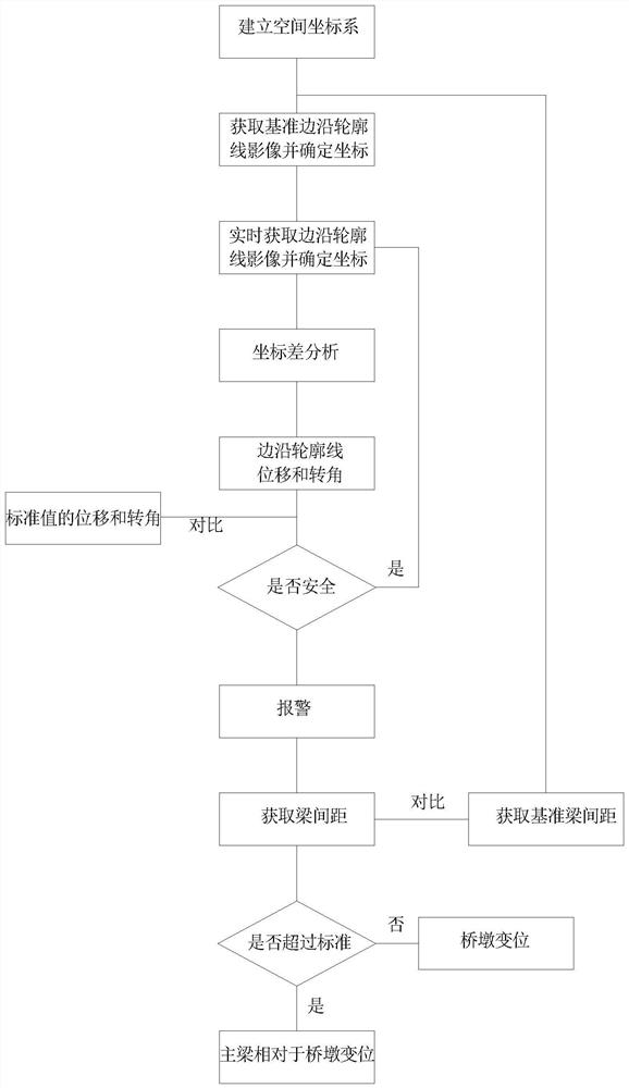
[0042] The method for monitoring the safety state of the pier-beam support connection part of the present invention comprises the following steps:

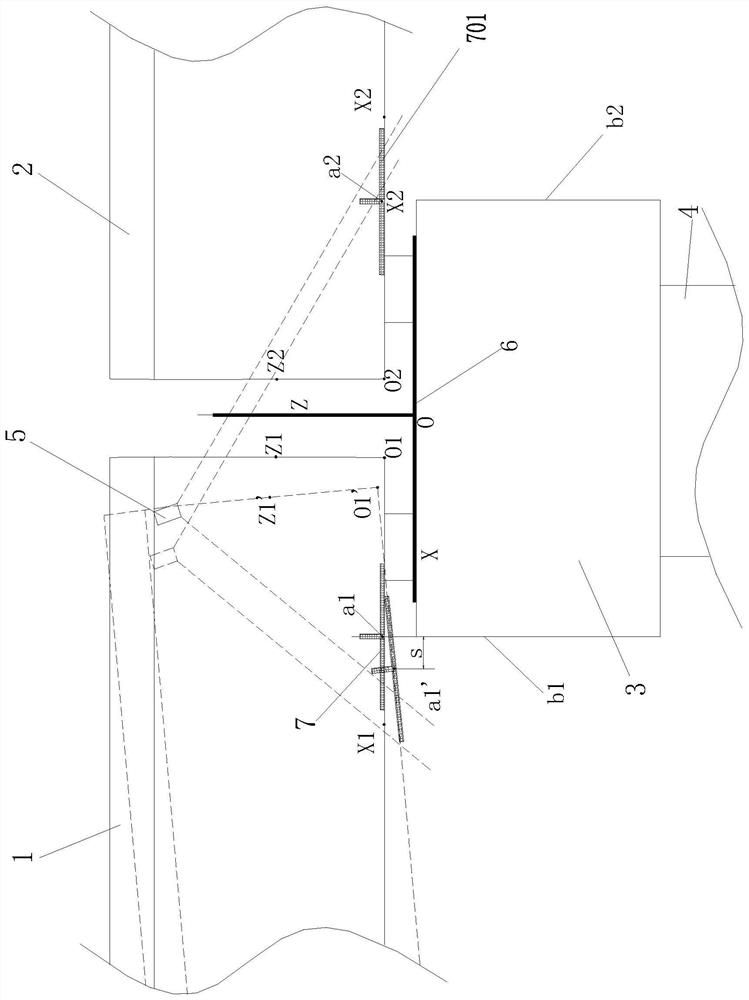
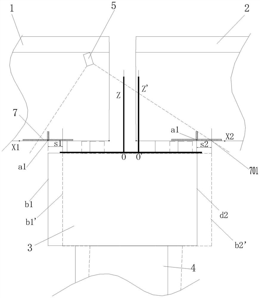
[0043] a. Establish a spatial coordinate system, the origin of which is located near the supporting connection between the main girder and the bridge pier;

[0044] b. Obtain the main girder 1 by taking a camera (two main girders are supported and connected on one pier, as shown in the figure, main girder 1 and main girder 2, in the embodiment of the present invention, the displacement of the main girder is mainly based on the main girder 1 For example) the edge contour line of the web, and determine the coordinates of the edge contour in the space coordinate system; the camera's field of view (the range where the dotted line corresponding to the camera 5 in the figure) position should be able to photograph the web The edge contour line, which includes the edge contour line at the end and the edge contour line at the bottom, can r...


PUM


Abstract

The invention discloses a method for monitoring a safety state of a pier-beam bearing connection part. The method comprises the following steps of: obtaining coordinates of a contour line of a main beam end face (a support connection part) through fixed-point or multi-view photography, comparing the coordinates with coordinates in different periods to obtain a coordinate difference, analyzing the coordinate difference, and obtaining displacement and deflection data of the contour line in different periods; and evaluating and predicting the safety condition of the structure according to analysis of previous displacement and deflection data. The whole process is simple and convenient, hidden danger diseases related to safety of the main beam and pier supporting connection structure can be found economically, efficiently, timely and accurately, and safe use of a bridge is ensured; the equipment adopted by the method is low in manufacturing cost and convenient to install and maintain (operation is conducted only on the pier top); the obtained information is comprehensive, and the displacement and corner information of the beam end basically reflects the overall condition of the main beam structure, so that the pier-beam connection state is reflected comprehensively and accurately.

Description

technical field [0001] The invention belongs to the field of engineering structure safety monitoring / detection maintenance, and in particular relates to a method for monitoring the safety state of a pier-beam support connection part. Background technique [0002] Conventional span bridges account for about 90% of the total mileage of bridges. The main girder of conventional span bridges generally adopts simply supported girders or continuous girders, and the non-fixed connection method with special supports is usually used between them and the pier. The advantage is that it can It is better adapted to the thermal expansion and contraction deformation of the main girder under the change of ambient temperature; but there are also accidental loads (such as vibration, impact, lateral horizontal force or bias pressure or accidental loads such as earthquakes), which cause excessive displacement of the main girder or bridge piers Deformation, leading to the risk of major safety acc...

Claims


Application Information

Patent Timeline
Patent Type & Authority Applications(China)
IPC IPC(8): G01B11/00G01B11/02G01B11/24G01M5/00
CPCG01B11/002G01B11/022G01B11/24G01M5/0008
Inventor 周志祥马燕飞楚玺吴桐朱伟铸衡俊霖罗瑞孟俊豪
Owner SHENZHEN UNIV
Why Eureka
Try Eureka