Optical imaging element with magnetic reflective layer imaging unit and preparation method thereof

An optical imaging and imaging unit technology, applied in optical components, optics, instruments, etc., can solve problems such as insufficient resolution and clarity of aerial imaging, restrictions on commercial promotion and large-scale application of medium-free aerial imaging technology, and impact on user experience. , to achieve the effect of low insertion loss, increased dielectric constant, and elimination of influence

Active Publication Date: 2022-04-29
XIANGHANG SHANGHAI TECH CO LTD +3
View PDF0 Cites 0 Cited by
  • Summary
  • Abstract
  • Description
  • Claims
  • Application Information

AI Technical Summary

Problems solved by technology

In the above-mentioned high-tech fields, optical components are widely used, but the surface quality requirements of optical components are relatively high. However, the micro-channel matrix optical waveguide plate realized by two layers of orthogonally arranged transparent materials is now used. The resolution and definition of aerial imaging are not enough, which not only affects the user experience, but also puts forward higher requirements for application scenarios, which greatly restricts the commercial promotion and large-scale application of mediumless aerial imaging technology.

Method used


Image

  • Optical imaging element with magnetic reflective layer imaging unit and preparation method thereof
  • Optical imaging element with magnetic reflective layer imaging unit and preparation method thereof
  • Optical imaging element with magnetic reflective layer imaging unit and preparation method thereof

Examples


Embodiment 1

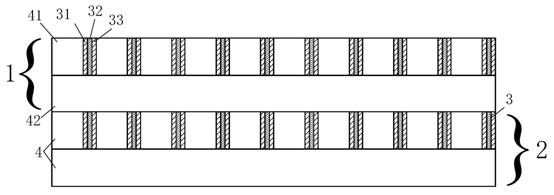
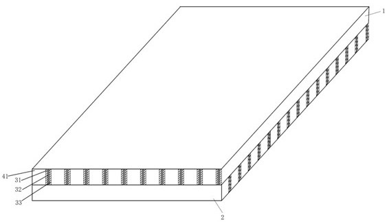
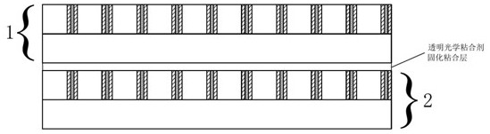
[0053] Such as Figure 1-2 As shown, the optical imaging element provided in this embodiment has a magnetic reflective layer imaging unit, the optical imaging element includes a superimposed optical imaging unit, and the optical imaging unit includes an upper transparent laminated body 1 and a lower transparent laminated body 2, The upper light-transmitting laminated body 1 and the lower-layer light-transmitting laminated body 2 have the same structure, and are composed of several light-transmitting strips 4 with reflective layers 3 arranged side by side. The direction of the light strip 41 is perpendicular to the direction of the second light-transmitting strip 42 in the lower light-transmitting laminated body 2;

[0054] The reflective layer 3 is a sandwich laminated metal magnetic thin layer, and the sandwich laminated metal magnetic thin layer 3 includes a first metal aluminum layer 31, a central magnetic layer 32 and a second metal aluminum layer 33, the first metal alumi...

Embodiment 2

[0056] The optical imaging element provided in this embodiment has a magnetic reflective layer imaging unit. The optical imaging element includes two superimposed optical imaging units. The optical imaging unit includes an upper transparent laminated body 1 and a lower transparent laminated body 2. The body 1 and the lower light-transmitting laminated body 2 have the same structure, and are composed of several light-transmitting strips 4 with reflective layers 3 arranged side by side. It is characterized in that the first light-transmitting strip 41 in the upper light-transmitting laminated body set perpendicular to the direction of the second light-transmitting strip 42 in the lower light-transmitting laminated body 2;

[0057] The reflective layer 3 is a sandwich laminated metal magnetic thin layer, and the sandwich laminated metal magnetic thin layer 3 includes a first metal aluminum layer 31, a central magnetic layer 32 and a second metal aluminum layer 33, the first metal ...

Embodiment 3

[0059] This embodiment provides an optical imaging element with a magnetic reflective layer imaging unit, the optical imaging element includes 5 superposed optical imaging units, the optical imaging unit includes an upper transparent laminated body 1 and a lower transparent laminated body 2, and the upper transparent laminated body 1 and the lower light-transmitting laminated body 2 have the same structure, and are composed of several light-transmitting strips 4 with reflective layers 3 arranged side by side. The directions of the second light-transmitting strips 42 in the lower light-transmitting laminated body 2 are vertically intersecting;

[0060] The reflective layer 3 is a sandwich laminated metal magnetic thin layer, and the sandwich laminated metal magnetic thin layer 3 includes a first metal aluminum layer 31, a central magnetic layer 32 and a second metal aluminum layer 33, the first metal aluminum layer 31 and the second metal aluminum layer 33 sandwich the central ...


PUM

PropertyMeasurementUnit
thicknessaaaaaaaaaa
thicknessaaaaaaaaaa
thicknessaaaaaaaaaa

Abstract

The invention provides an optical imaging element with a magnetic reflection layer imaging unit and a preparation method thereof. The optical imaging element includes several superimposed optical imaging units. The optical imaging unit includes an upper light-transmitting laminate and a lower light-transmitting laminate, and the upper light-transmitting laminate The body and the lower light-transmitting laminate are composed of several light-transmitting strips with a reflective layer in parallel, and the direction of the first light-transmitting strip in the upper-layer light-transmitting laminate and the direction of the second light-transmitting strip in the lower light-transmitting laminate are in the same direction. The reflective layer is a sandwich laminated metal magnetic thin layer, which includes a first metal aluminum layer, a central magnetic layer and a second metal aluminum layer. The present invention can form a binary magneto-optical photonic crystal with a building block structure, or a ternary magneto-optical photonic crystal structure when a plurality of optical imaging units are stacked, and the non-reciprocal effect at the edge of the forbidden band is maximized. The shift region realizes a non-reciprocal phase shift region without a huge thickness, reduces light loss, and improves the accuracy of refraction imaging.

Description

technical field [0001] The invention belongs to the technical field of optical imaging elements, and in particular relates to an optical imaging element with a magnetic reflective layer imaging unit and a preparation method thereof. Background technique [0002] In recent years, with the rapid development of cutting-edge technologies such as aerospace technology, optoelectronic technology, atomic energy technology and laser technology, the performance requirements for optical components are also getting higher and higher. In the above-mentioned high-tech fields, optical components are widely used, but the surface quality requirements of optical components are relatively high. However, the micro-channel matrix optical waveguide plate realized by two layers of orthogonally arranged transparent materials is now used. The resolution and definition of aerial imaging are not enough, which not only affects the user experience, but also puts forward higher requirements for applicati...

Claims


Application Information

Patent Timeline
Patent Type & Authority Patents(China)
IPC IPC(8): G02B1/00C09J151/00C09J11/04C08F265/06
CPCG02B1/005C09J151/003C09J11/04C08F265/06C08K2003/2244C08K3/22
Inventor 郝雅棋张兵
Owner XIANGHANG SHANGHAI TECH CO LTD
Why Eureka
Try Eureka