Relay

A relay and armature technology, applied in relays, non-polar relays, electromagnetic relays, etc., can solve the problems of inability to build hybrid circuit breakers, increased disconnection time, and long contact disconnection time

Pending Publication Date: 2022-02-25
EATON INTELLIGENT POWER LTD
View PDF1 Cites 0 Cited by
  • Summary
  • Abstract
  • Description
  • Claims
  • Application Information

AI Technical Summary

Problems solved by technology

[0007] A disadvantage of known or available relays is that their contact opening time is too long to build a compact hybrid circuit breaker
Another disadvantage is that the turn-off time increases with several switching cycles

Method used


Image

  • Relay
  • Relay
  • Relay

Examples


Embodiment Construction

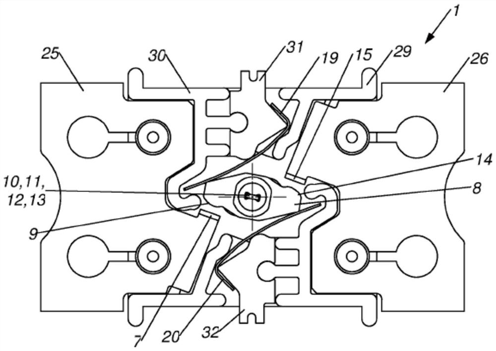
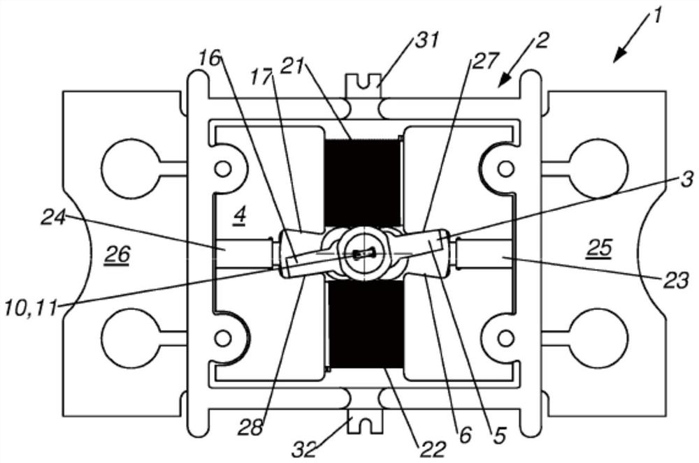
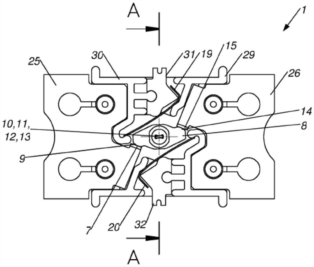
[0023] figure 1 5 shows a relay 1 comprising an electromagnetic drive unit 2 with a rotatable armature 3 comprising a first magnetic contact area 5 and a yoke 4 comprising a second magnetic contact area 6 and a first magnetic contact area 6. The contact area 5 is in contact with the second magnetic contact area 6 in the first state of the relay 1, the relay 1 further comprising at least a non-movable first electrical contact 7 and a movable contact arm 8 having at least a second electrical contact 9, In the first state, the first electrical contact 7 is in contact with the second electrical contact 9 , wherein the armature 3 and the contact arm 8 are arranged together on the shaft 10 and are embodied together with the shaft 10 as a torsion element 11 .

[0024] Therefore, the relay 1 according to the invention has a high contact pressure resulting in a low resistance. The relay 1 has no air gap between the yoke 4 and the armature 3, resulting in a low power demand on the coil...


PUM


Abstract

A relay (1) comprising an electromagnetic drive unit (2) with a rotatable armature (3) and a yoke (4), the armature (3) comprises a first magnetic contact region (5), the yoke (4) comprises a second magnetic contact region (6), the first magnetic contact region (5) being in touch with the second magnetic contact region (6) in a first state of the relay (1), the relay (1) further comprises at least an immovable first electric contact (7) and a moveable contact arm (8) with at least a second electric contact (9), the first electric contact (7) contacts the second electric contact (9) in the first state is suggested, with the armature (3) and the contact arm (8) are arranged together on a shaft (10), and with the shaft (10) is embodied as torsional element (11).

Description

technical field [0001] The invention relates to a relay according to the general part of claim 1 . Background technique [0002] Electromagnetic relays are well known and are part of many electrical devices. Even in the days of semiconductor switching elements, classic mechanical relays have the advantage of low resistance and low dissipated energy. [0003] Electromagnetic relays are part of so-called hybrid switchgear, especially hybrid circuit breakers (HCB). Hybrid switchgear consists of semiconductor switching units that are shunted by relays. Such relays are often referred to as bypass relays. In normal operation, the contacts of the bypass relay are closed and the semiconductor switching unit is normally in non-conducting mode. The semiconductor switching unit can also be in a conducting or semi-conducting mode. Current through the switching device flows through a low resistance bypass relay. [0004] For short-circuit breaking operation, bypass relays must open...

Claims


Application Information

Patent Timeline
Patent Type & Authority Applications(China)
IPC IPC(8): H01H50/54H01H3/32
CPCH01H50/54H01H3/32H01H3/3042H01H9/542H01H51/2272H01H50/56H01H36/00H01H50/24H01H50/60H01H50/643H01H50/648H01H51/14
Inventor M·卡岑施泰内尔A·海默尔
Owner EATON INTELLIGENT POWER LTD
Why Eureka
Try Eureka