Control method of cleaning machine

A control method and cleaning machine technology, applied to cleaning machinery, cleaning equipment, carpet cleaning, etc., can solve the problems of motors being easily damaged, slipping, and moving paths, etc., and achieve simple overall structure, good linear movement, and clean good effect

Active Publication Date: 2022-03-01
QUFU SINODOD INTELLIGENT TECH CO LTD
View PDF8 Cites 0 Cited by
  • Summary
  • Abstract
  • Description
  • Claims
  • Application Information

AI Technical Summary

Problems solved by technology

[0005] For this reason, the object of the present invention is to provide the control method of cleaning machine, mainly solves the problem that existing cleaning machines that use two mop cloths as the moving power source cannot adjust the frictional force of the two mop cloths relative to the ground and cause the moving path to easily deviate , Steering movement is easy to slip, unable to avoid obstacles well, and the motor is easily damaged

Method used


Image

  • Control method of cleaning machine
  • Control method of cleaning machine
  • Control method of cleaning machine

Examples


Embodiment

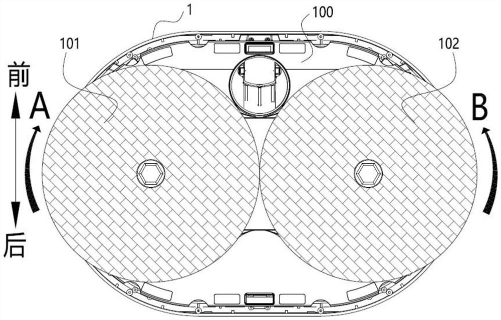
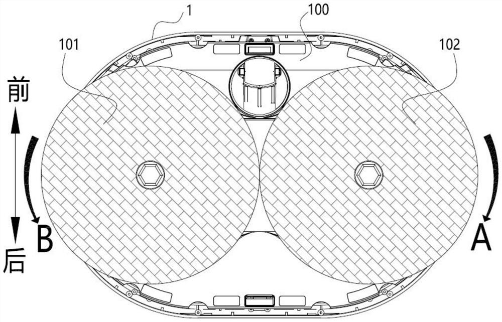
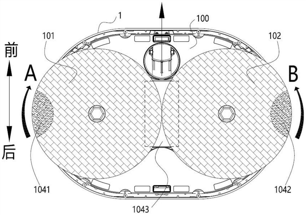
[0047] Embodiment: the control method of cleaning machine of the present invention, as Figure 1 to Figure 8 As shown in the configuration, the cleaning machine 1 is mainly used to move and walk on the ground for mopping and cleaning. Specifically, the cleaning machine 1 is provided with a first rotating drag member 101 and a second rotating dragging member 102 to mop and clean the ground. The first rotary dragging part 101 and the second rotary dragging part 102 are arranged as a structure that can rotate horizontally. At the same time, the cleaning machine 1 of this program does not need to be provided with driving wheels to drive and move, and the first rotary dragging part 101 and the second rotary dragging part The rotational power of 102 is used as the power source for the movement of the cleaning machine 1, and the overall structure of the cleaning machine 1 is simple and low in cost.

[0048] The cleaning machine 1 includes a machine main body 100. The machine main bod...


PUM


Abstract

According to the control method of the cleaning machine, the cleaning machine comprises a machine body, the machine body comprises a first rotary mopping piece and a second rotary mopping piece, and the first rotary mopping piece and the second rotary mopping piece are each arranged to be of a structure capable of being attached to the ground to horizontally rotate and move; the first rotary dragging piece and the second rotary dragging piece rotate horizontally and control the cleaning machine to move in the first direction; when an obstacle exists in the first moving direction of the cleaning machine, the method at least comprises the step of controlling the first rotary dragging piece and/or the second rotary dragging piece to change the pressure so as to correspondingly enable the first rotary dragging piece and/or the second rotary dragging piece to control the cleaning machine to move in the second direction; when the first rotary mopping piece and the second rotary mopping piece make contact with the ground and rotate horizontally, unbalanced friction force is formed to serve as a power source for movement of the cleaning machine. According to the scheme, the problems that according to an existing cleaning machine with two mops as moving power sources, the moving path is prone to deviation, slipping is prone to occurring in steering movement, obstacles cannot be well avoided, and a motor is prone to being damaged are solved.

Description

technical field [0001] The invention relates to the field of floor cleaning, in particular to a control method for a cleaning machine that moves on the floor to clean the floor. Background technique [0002] Existing cleaning machines are generally equipped with drive wheels to drive the cleaning machine to move on the ground, and a mop is set on the cleaning machine, and the cleaning machine drives the mop to move synchronously during the movement to realize the mopping and cleaning of the ground. The setting causes the distribution structure of the mop to be limited, and it is impossible to reasonably arrange the structure between the mop and the driving wheel to increase the area of ​​the mop. At the same time, the setting of the driving wheel leads to a complex overall structure and high cost of the cleaning machine. [0003] Some cleaning machines mop the floor by setting two mops that rotate horizontally. At the same time, they also use two mops to drive the cleaning m...

Claims


Application Information

Patent Timeline
Patent Type & Authority Applications(China)
IPC IPC(8): A47L11/40A47L11/282
CPCA47L11/4011A47L11/4066A47L11/4038A47L11/4061A47L11/282
Inventor 高新忠高令宇方恩光甘嵩吴久东王超邓杰
Owner QUFU SINODOD INTELLIGENT TECH CO LTD
Why Eureka
Try Eureka