
Thrombus collecting device

A technology for collecting devices and thrombus, which is applied in the field of medical devices and can solve problems such as fragmentation, complicated surgical operations, and poor ability to place in blood vessels

Pending Publication Date: 2022-03-01
BEIJING TAIJIE WEIYE TECH
View PDF12 Cites 4 Cited by
  • Summary
  • Abstract
  • Description
  • Claims
  • Application Information

AI Technical Summary

Problems solved by technology

[0002] The currently widely used thrombectomy stents are used in the treatment of acute ischemic stroke, such as the Solitaire stent of Medtronic or the Trevo XP stent of Stryker, which are usually used in combination with ordinary access catheters or intermediate catheters (such as ev3 company Navien catheter and Microvention’s Sofia catheter, etc.), during the thrombectomy process, the access catheter or intermediate catheter is usually located at the proximal end of the thrombus site, while the thrombus retrieval stent reaches the thrombus site with the help of a thinner microcatheter, after the stent is released in situ The thrombus is embedded through self-expansion. After the stent is fully opened, the doctor pulls the stent along the proximal direction of the blood vessel through the stent guide wire, and recovers the thrombus into the access catheter or intermediate catheter. During the process of pulling the thrombus, the thrombus is squeezed And the moment it enters the inner cavity of the distal end of the catheter, it is easy to be crushed and broken, and some broken thrombi are bound to escape to the proximal end outside the catheter (there is a large gap between the catheter and the inner wall of the blood vessel, and the thrombus is squeezed at the moment of extrusion). It is easy to break and escape), although in recent years there has been a proximally protected balloon guide catheter, but due to the larger outer diameter and higher hardness of the balloon guide catheter, the ability to place in the blood vessel is poor (distance from the actual thrombus The site is far away), and due to the use of the balloon guide catheter, the operation will be more complicated, and it will also increase the cost of the operation

Method used


Image

  • Thrombus collecting device
  • Thrombus collecting device
  • Thrombus collecting device

Examples


Embodiment Construction

[0042] The technical solution of the present disclosure will be described in further detail below with reference to the drawings and embodiments.

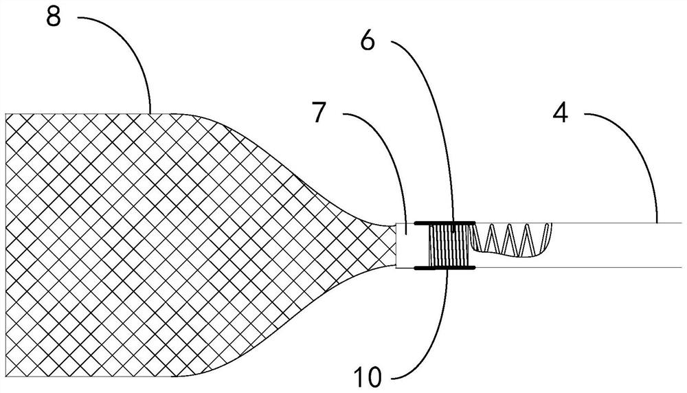
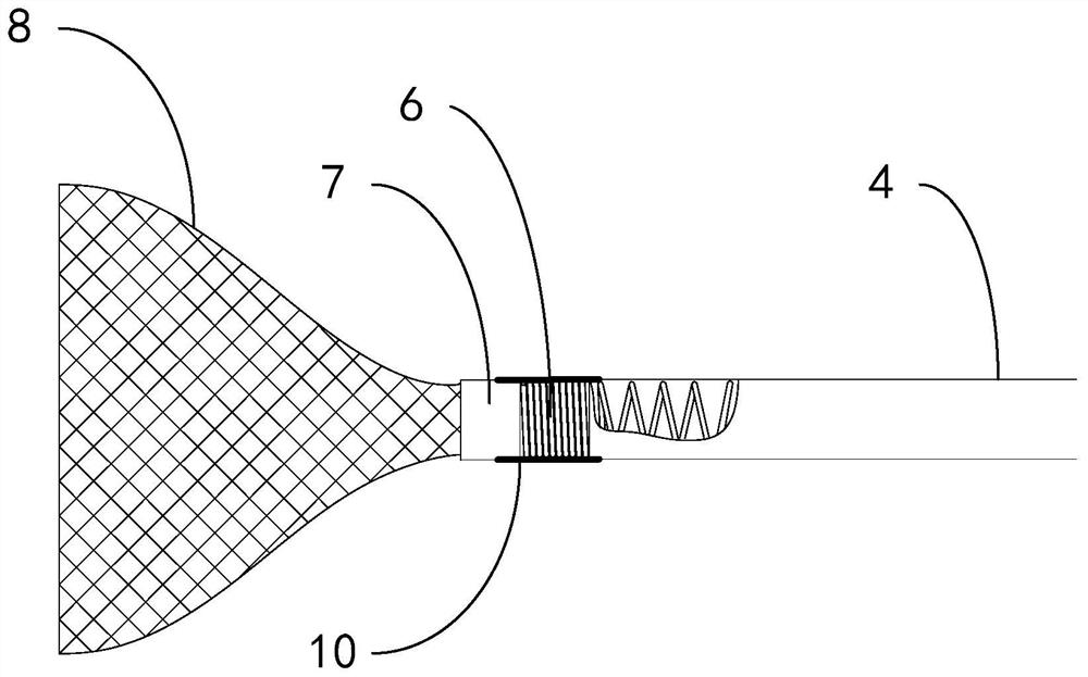
[0043] An embodiment of the present disclosure provides a thrombus collection device, which includes an outer catheter and an inner catheter. The proximal end of the outer catheter is sequentially connected to a distal tube seat and a hemostatic valve. inside the cavity. The distal end of the inner catheter is connected with a hollow marker tube through a spring connector, the hollow marker tube has an annular cavity, the proximal end of the collection basket is inserted into the annular cavity of the hollow marker tube, and the collection basket can be Automatically open and close to the inner wall of the blood vessel to realize the collection of thrombus and effectively prevent the thrombus from escaping during thrombus removal.

[0044] The present disclosure will be described in detail through specific examples below, but it s...


PUM


Abstract

The invention relates to a thrombus collecting device which is composed of an outer catheter and an inner catheter, the far end of the inner catheter is connected with a hollow marking tube through a spring connecting piece, the hollow marking tube is provided with an annular cavity, and the near end of a collecting net basket is inserted into the annular cavity of the hollow marking tube. The collection net basket can be automatically opened and tightly attached to the inner wall of the blood vessel after extending out of the outer catheter, thrombus collection is achieved, the situation that thrombus escapes during thrombus extraction can be effectively prevented, and the occurrence probability of intraoperative and postoperative complications is reduced.

Description

technical field [0001] The present disclosure relates to the field of medical devices, in particular to a thrombus collection device. Background technique [0002] The currently widely used thrombectomy stents are used in the treatment of acute ischemic stroke, such as the Solitaire stent of Medtronic or the Trevo XP stent of Stryker, which are usually used in combination with ordinary access catheters or intermediate catheters (such as ev3 company Navien catheter and Microvention’s Sofia catheter, etc.), during the thrombectomy process, the access catheter or intermediate catheter is usually located at the proximal end of the thrombus site, while the thrombus retrieval stent reaches the thrombus site with the help of a thinner microcatheter, after the stent is released in situ The thrombus is embedded through self-expansion. After the stent is fully opened, the doctor pulls the stent along the proximal direction of the blood vessel through the stent guide wire, and recovers...

Claims


Application Information

Patent Timeline
Patent Type & Authority Applications(China)
IPC IPC(8): A61B17/221
CPCA61B17/221A61B2017/2215
Inventor 许永松韩雪倩郭琦穆磊唐航廖芝美刘昊王锐
Owner BEIJING TAIJIE WEIYE TECH
Learn More