Cervical vertebra positioning device and operating bed
A cervical vertebra positioning and operating bed technology, which is applied in the field of cervical vertebra positioning devices and operating beds, can solve the problems of inability to ensure the consistency of patients and cone postures, and achieves the effect of improving surgical safety, surgical success rate, and ensuring accuracy.
- Summary
- Abstract
- Description
- Claims
- Application Information
AI Technical Summary
Problems solved by technology
Method used
Image
Examples
Embodiment 1
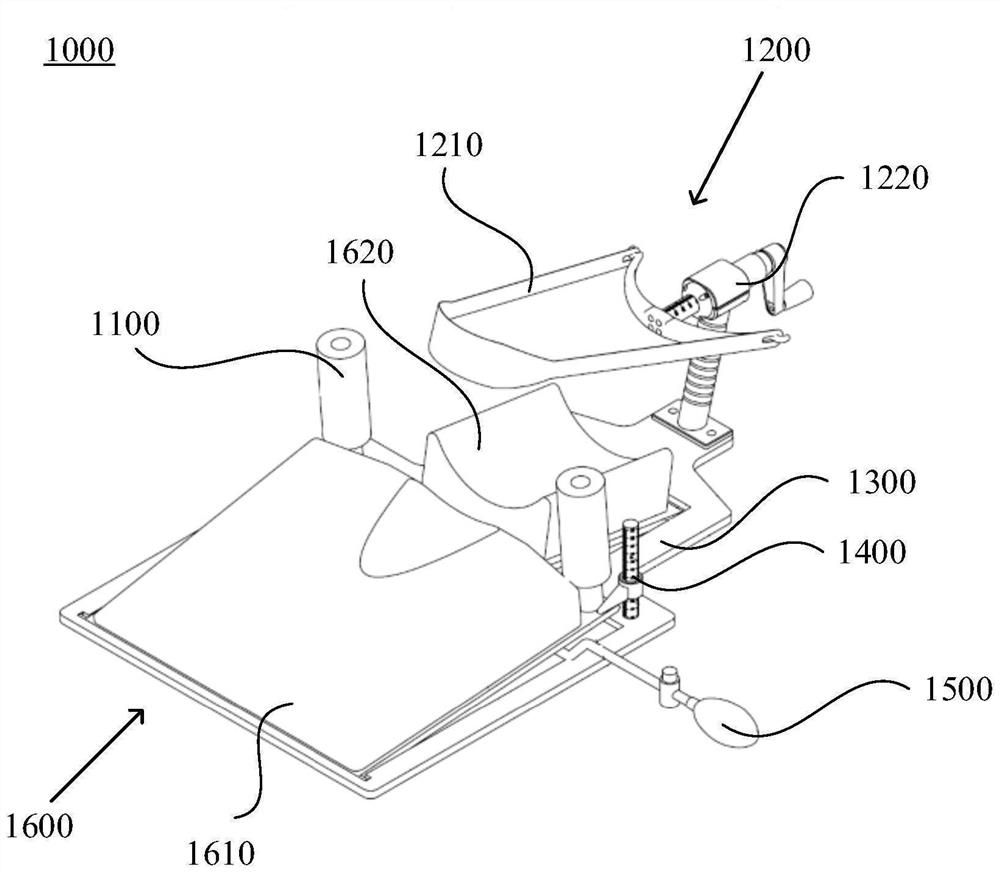
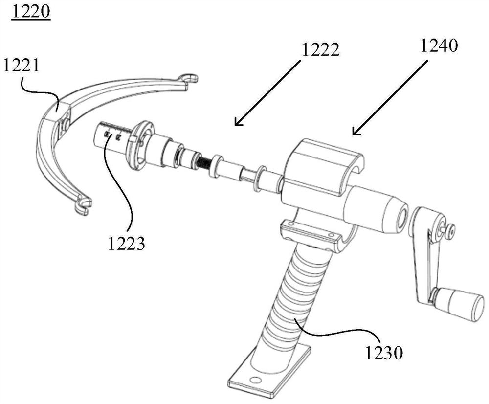
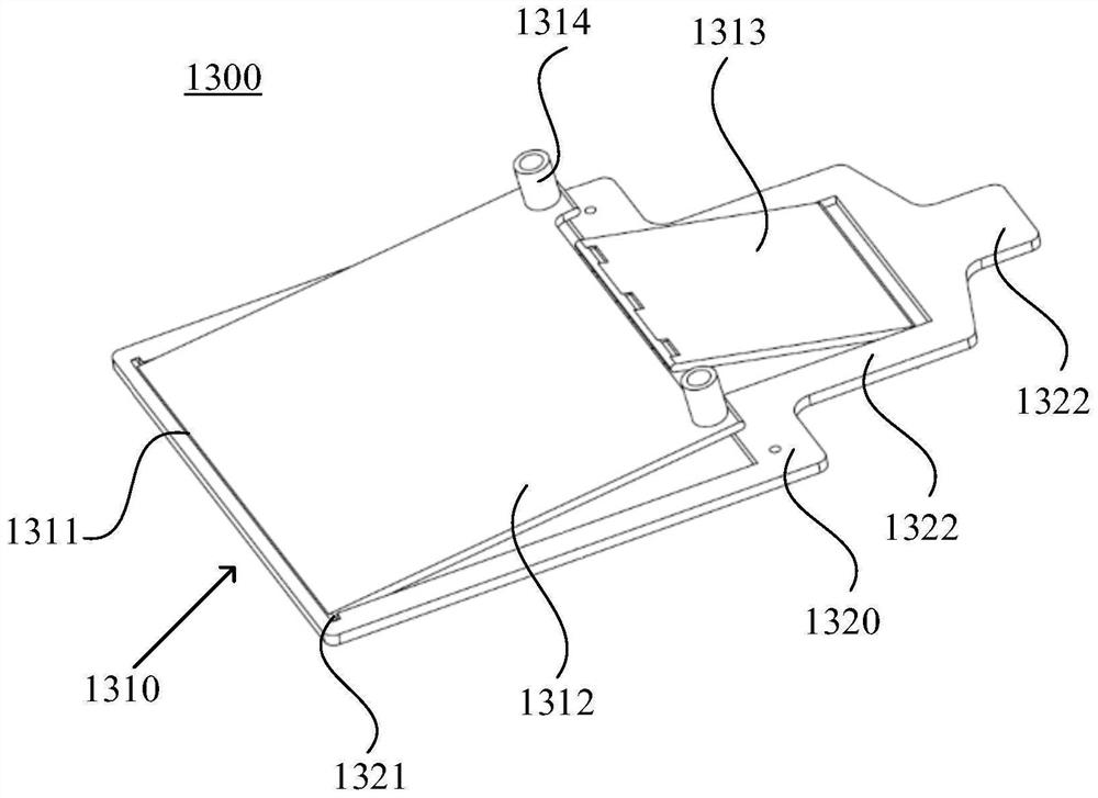
[0145] Such as Figure 1-Figure 5 As shown, the present embodiment provides a cervical spine positioning device 1000. The cervical spine positioning device 1000 includes: a shoulder rest assembly 1100, which is arranged on the operating bed to resist the patient's shoulder; a traction assembly 1200, a traction assembly 1200 Set on the operating bed, the traction assembly 1200 drives the patient's head to move in a direction close to the traction assembly 1200 by constraining the patient's jaw; the floor assembly 1300, the shoulder rest assembly 1100 and the traction assembly 1200 are all arranged on the floor assembly 1300, and the patient lies on On the base plate assembly 1300, the height of the base plate assembly 1300 relative to the operating bed can be adjusted to adjust the height of the patient.
[0146] In a specific implementation, there are two shoulder rest assemblies 1100, and the two shoulder rest assemblies 1100 respectively bear against the patient's shoulders ...
Embodiment 2
[0194] This embodiment is a cervical spine positioning device and an operating bed. The pushing part 1222 in Embodiment 1 is the pushing part 51 in this embodiment, and the supporting part 1230 in Embodiment 1 is the supporting part 54 in this embodiment. The guide part 1240 in Example 1 is the guide part 55 in this embodiment.
[0195] Such as Figure 6-Figure 10 As shown, the present embodiment provides a cervical vertebra positioning device 400. The cervical vertebra positioning device 400 includes a shoulder rest assembly 4 and a head clamp assembly 5. The shoulder rest assembly 4 is arranged on the operating bed and is against the shoulder of the patient. The head clamp assembly 5 is arranged on the operating bed, and the head clip assembly 5 is against the patient's head to fix the patient's head.
[0196] In practice, the patient is lying on the operating bed, and there are two shoulder rest assemblies 4, and the two shoulder rest assemblies 4 respectively abut against...
Embodiment 3
[0257] This embodiment is a connecting device and a traction bed, and the steering part 53 in Embodiment 2 is the connecting device 100 in this embodiment.
[0258] One end of the connecting device 100 is connected to the clamping part 52, and the other end of the connecting device 100 is connected to the pushing part 51, and the pushing part 51 pushes the clamping part 52 by pushing the connecting device 100, and the clamping part 52 can be adjusted by the connecting device 100 Angle, after being adjusted to a desired angle, the connecting device 100 can fix the clamping portion 52 at the desired angle through self-locking.
[0259] Such as Figure 11-Figure 22 As shown, this embodiment provides a connection device 100, the connection device 100 is arranged between the traction shoe and the traction frame, the connection device 100 includes: a first connection part 1, the first connection part 1 is connected to the traction shoe, the first connection The part 1 is provided w...
PUM
 Abstract
Description
Claims
Application Information
 - R&D
- Intellectual Property
- Life Sciences
- Materials
- Tech Scout
- Unparalleled Data Quality
- Higher Quality Content
- 60% Fewer Hallucinations
Browse by: Latest US Patents, China's latest patents, Technical Efficacy Thesaurus, Application Domain, Technology Topic, Popular Technical Reports.
© 2025 PatSnap. All rights reserved.Legal|Privacy policy|Modern Slavery Act Transparency Statement|Sitemap|About US| Contact US: help@patsnap.com


