Convenient-to-use clinical debridement device for dermatology department

A dermatological and convenient technology, applied in the field of clinical debridement, can solve the problems of secondary injury of patients, pollution of medical environment, sputtering to places other than debridement devices, etc., to ensure normal progress, reduce secondary injury, avoid sewage splash effect

Inactive Publication Date: 2022-03-01
鄂东医疗集团市中心医院
View PDF0 Cites 0 Cited by
  • Summary
  • Abstract
  • Description
  • Claims
  • Application Information

AI Technical Summary

Problems solved by technology

[0003] However, most patients place their upper limbs directly on the debridement platform during debridement of upper limb wounds, and some patients even hang their upper limbs in the air for medical staff to handle. In this way, during the debridement process, patients It is difficult to maintain the same posture for a long time, and at the same time, the pain generated during debridement exacerbates the possibility of the patient's limbs moving. At the same time, in the process of debridement, some blood and flushing sewage will inevitably be produced. If the patient has a large range of activities, the sewage may be splashed to places other than the debridement device, causing pollution to the medical environment; in addition, Most of the traditional debridement devices will install a collection device such as a trash can at the bottom of the device to collect the garbage generated during the debridement process. However, if the collection device is placed directly at the bottom of the debridement device, it is easy to be damaged when the debridement device moves. The collision produces a rollover situation, which will cause pollution to the medical environment

Method used


Image

  • Convenient-to-use clinical debridement device for dermatology department
  • Convenient-to-use clinical debridement device for dermatology department
  • Convenient-to-use clinical debridement device for dermatology department

Examples


Embodiment Construction

[0024] In order to make the technical means, creative features, goals and effects achieved by the present invention easy to understand, the present invention will be further described below in conjunction with specific embodiments.

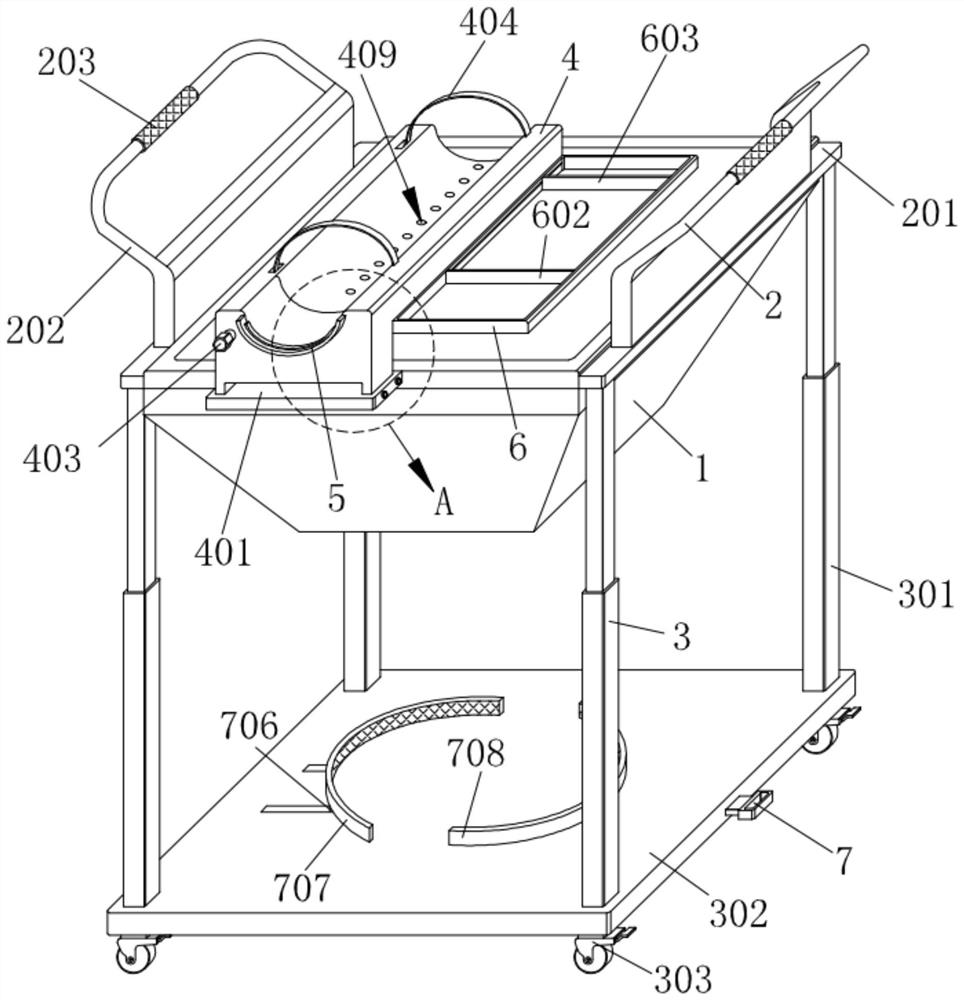
[0025] Such as Figure 1-Figure 6 As shown, a convenient dermatology clinical debridement device according to the present invention includes a receiving frame 1, an operating mechanism 2 is provided on the receiving frame 1, a supporting mechanism 3 is provided on the receiving frame 1, and the receiving frame 1 is provided with a supporting mechanism 3. The receiving frame 1 is provided with a limit mechanism 4, the limit mechanism 4 is provided with a protective mechanism 5 and an auxiliary mechanism 6, and the support mechanism 3 is provided with a fastening mechanism 7;

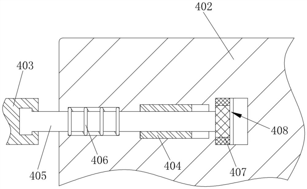
[0026]The limit mechanism 4 includes a support block 401, the support block 401 is fixedly connected to the receiving frame 1, the support block 401 is equipped with a placem...


PUM


Abstract

The invention relates to the technical field of clinical debridement, in particular to a dermatological clinical debridement device convenient to use, which comprises a bearing frame, an operating mechanism, a supporting mechanism and a limiting mechanism are arranged on the bearing frame, and a protection mechanism and an auxiliary mechanism are arranged on the limiting mechanism. A fastening mechanism is arranged on the supporting mechanism; the limiting mechanism is arranged on the bearing frame, the injured upper limbs of the patient can be conveniently and temporarily limited and fixed, the situation that the movement range of the upper limbs of the patient is large during debridement is avoided, and therefore normal debridement work is guaranteed; through the cooperation of the limiting mechanism and the protection mechanism, sewage generated during debridement can be conveniently blocked and guided, and meanwhile, the situation that the sewage is splashed due to the fact that the movement range of a patient is large is avoided; and through the fastening mechanism, the garbage collecting device arranged on the supporting mechanism can be conveniently limited and fixed, and the garbage collecting device is prevented from rolling over due to collision when the debridement device is moved.

Description

technical field [0001] The invention relates to the technical field of clinical debridement, in particular to a convenient clinical debridement device for dermatology. Background technique [0002] Debridement is a surgical method to remove foreign bodies in open wounds, remove necrotic, inactivated and heavily polluted tissues, and suture the wound to minimize pollution or even clean the wound, so as to achieve primary healing. . Debridement is mainly used in skin surgery, and more debridement is mainly aimed at extremity wounds. In the actual clinical process, in order to facilitate the debridement operation, there will be some devices and tools to assist the debridement operation. [0003] However, most patients place their upper limbs directly on the debridement platform during debridement of upper limb wounds, and some patients even hang their upper limbs in the air for medical staff to handle. In this way, during the debridement process, patients It is difficult to m...

Claims


Application Information

Patent Timeline
Patent Type & Authority Applications(China)
IPC IPC(8): A61M3/02
CPCA61M3/0266A61M3/02
Inventor 付曼妮石娴陈安尘罗小丹张金山
Owner 鄂东医疗集团市中心医院
Why Eureka
Try Eureka