Spreading type feeding device for quartz crystal wafers

A technology of quartz wafers and feeding devices, applied in conveyors, vibrating conveyors, transportation and packaging, etc., can solve problems such as low conveying efficiency, damaged wafers, overall size, energy consumption, vibration and noise, and reduce secondary damage Opportunities, improve the transmission efficiency, reduce the effect of vibration and noise

Pending Publication Date: 2019-07-12
RES INST OF ZHEJIANG UNIV TAIZHOU
View PDF16 Cites 0 Cited by
  • Summary
  • Abstract
  • Description
  • Claims
  • Application Information

AI Technical Summary

Problems solved by technology

Its design does not take into account the needs and characteristics of precision optical measurement. The automatic appearance sorting equipment for quartz wafers has the following obvious deficiencies: First, its output effect is piece by piece and fixed point. There will be stacks of wafers at the position of the tray, making it impossible for the feeding positioning camera to judge the wafer position, making it impossible for the pick-up nozzle to effectively remove the wafers, and even bumping and kicking the wafers to damage them; secondly, the spiral vibration feeding method transports the wafers from the bottom of the device to the exit It needs to go through a long spiral track, the conveying efficiency is low, and the surface of the wafer is prone to secondary scratch damage; third, the device is driven by a vibration motor, and the overall size, energy consumption and vibration noise are relatively large, which is different from that required by optical detection. Stable environment conflicts

Method used


Image

  • Spreading type feeding device for quartz crystal wafers
  • Spreading type feeding device for quartz crystal wafers
  • Spreading type feeding device for quartz crystal wafers

Examples


Embodiment Construction

[0027] The following will clearly and completely describe the technical solutions in the embodiments of the present invention with reference to the accompanying drawings in the embodiments of the present invention. Obviously, the described embodiments are some of the embodiments of the present invention, but not all of them. Based on the embodiments of the present invention, all other embodiments obtained by persons of ordinary skill in the art without making creative efforts belong to the protection scope of the present invention.

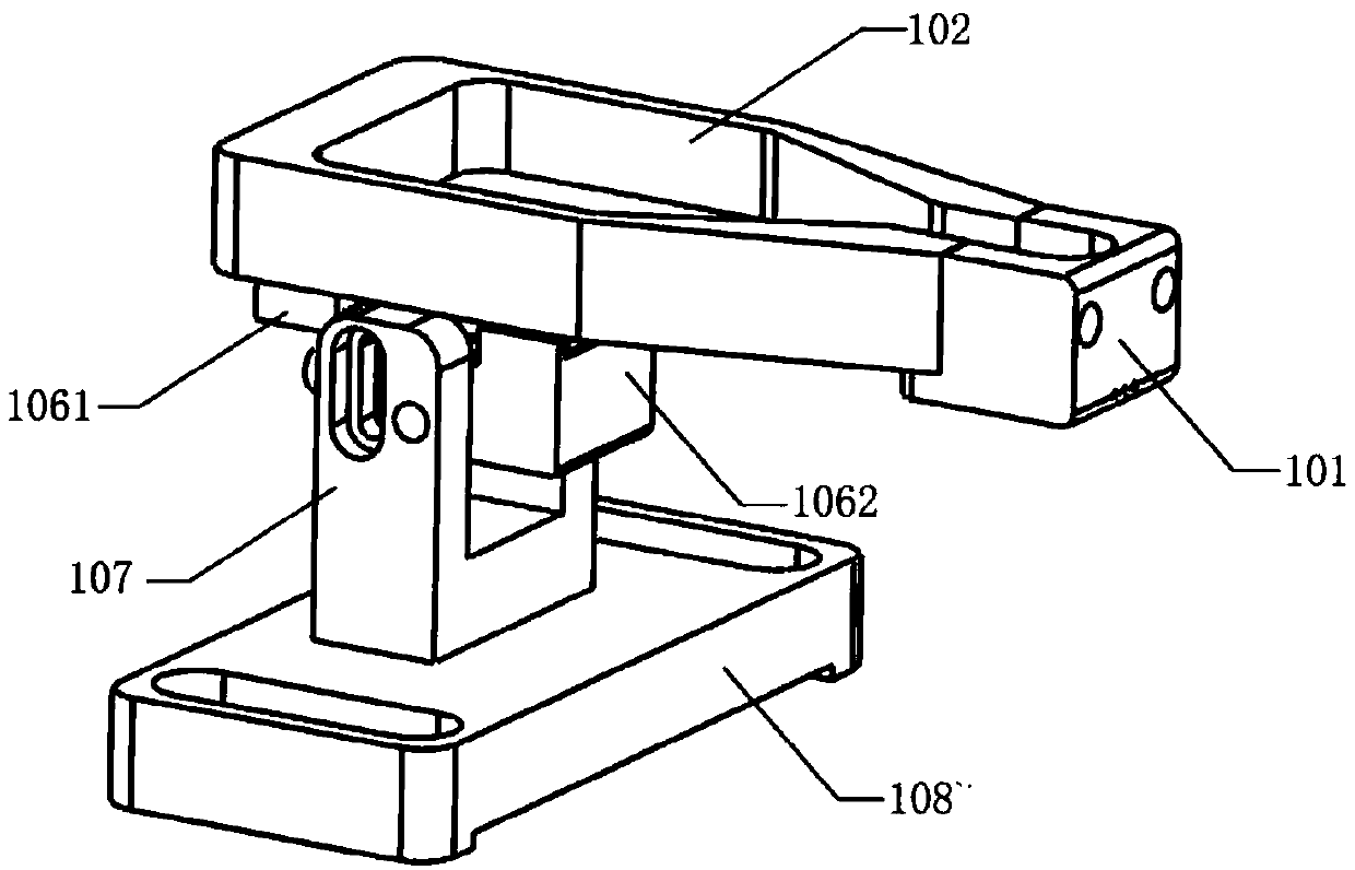
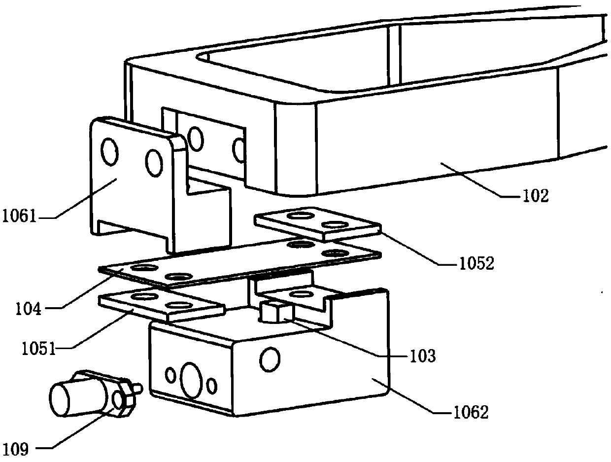
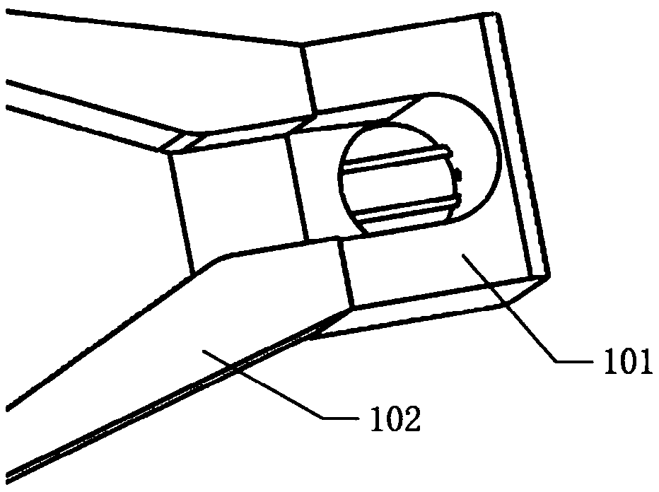
[0028] refer to Figure 1 to Figure 3 , the present invention discloses a disseminated feeding device for quartz wafers, comprising a feeding outlet 101, a material tray 102, a vibration source 103, a vibrating piece 104, a limiting piece, a vibrating block, a bracket 107 and a base 108, and the feeding outlet 101 uses a screw Installed on the front side of the material tray 102, the material tray 102 for carrying the quartz wafer is connected to ...


PUM


Abstract

The invention discloses a spreading type feeding device for quartz crystal wafers. The spreading type feeding device for the quartz crystal wafers comprises a feeding outlet, a material tray, a vibration source, a vibration piece, a limiting piece, a vibration block, a bracket and a base, wherein the feeding outlet is formed in the front side of the material tray, and the material tray for bearingthe quartz crystal wafers is connected with the vibration block through the feeding outlet; the vibration block and the vibration piece are in pressure connection through the limiting piece, and thevibration source is placed between the vibration block and the vibration piece and pressed tightly; the vibration source is located in a circular groove of the vibration block, and a signal wire of the vibration source is led out through an SMA interface; and the vibration block bears the material tray through the vibration piece, the vibration block is fastened on the bracket, the bracket is connected to the base, the base is used for being installed on quartz crystal wafer detection equipment, the quartz crystal wafers are placed in the material tray, when the vibration source outputs vibration energy with appropriate frequency and amplitude to drive the material tray to achieve mechanical resonance, the quartz crystal wafers in the tray slowly move linearly towards an outlet of the vibration tray and are evenly spread to the target area through the feeding outlet.

Description

technical field [0001] The invention belongs to the technical field of quartz wafer detection, and in particular relates to a spreading type feeding device for quartz wafers. Background technique [0002] Quartz crystal oscillator is a resonant device made by using the piezoelectric effect of quartz crystal (crystal of silicon dioxide). It is square, rectangular or circular, etc.), and its two corresponding surfaces are coated with silver layers as electrodes, and a lead is welded to each electrode to connect to the pin, and the package shell constitutes a quartz crystal. Crystal resonator, referred to as quartz crystal or crystal, crystal oscillator. Its products are generally packaged in metal shells, and some are packaged in glass shells, ceramics or plastics. Quartz crystal oscillators are high-precision and high-stability oscillators, which are widely used in various oscillating circuits such as color TVs, computers, remote controls, etc., as well as frequency gener...

Claims


Application Information

Patent Timeline
Patent Type & Authority Applications(China)
IPC IPC(8): B65G27/16B65G27/28B65G27/34
CPCB65G27/16B65G27/28B65G27/34
Inventor 郭彬孔丽微张林友袁国堂郑军章玮
Owner RES INST OF ZHEJIANG UNIV TAIZHOU
Why Eureka
Try Eureka