
Water outlet valve

A water outlet valve and water outlet technology, applied in the direction of spraying devices, etc., can solve the problems of fluid energy loss, low cleaning efficiency, and single function, and achieve the effects of reducing pressure loss, reasonable design, and ingenious structure

Active Publication Date: 2022-03-01
ZHEJIANG DANAU MASCH CO LTD
View PDF9 Cites 0 Cited by
  • Summary
  • Abstract
  • Description
  • Claims
  • Application Information

AI Technical Summary

Problems solved by technology

[0002] The existing water outlet valve mainly includes a water inlet port and a water outlet port on the valve body, and the flow or blocking of the liquid between the water inlet port and the water outlet port is adjusted by controlling the valve stem. It has a simple structure and a single function, and The hydraulic pressure of the liquid in the valve body will change due to the size of the pipeline, which will lead to the loss of fluid energy
[0003] At the same time, in the kitchen and bathroom for cleaning dishes or related places for cleaning large equipment, it is often necessary to add detergent to the water to form foam water to achieve the purpose of cleaning, but the mixing operation of detergent and water is relatively difficult. Inconvenient, low cleaning efficiency

Method used


Image

  • Water outlet valve
  • Water outlet valve

Examples


Embodiment Construction

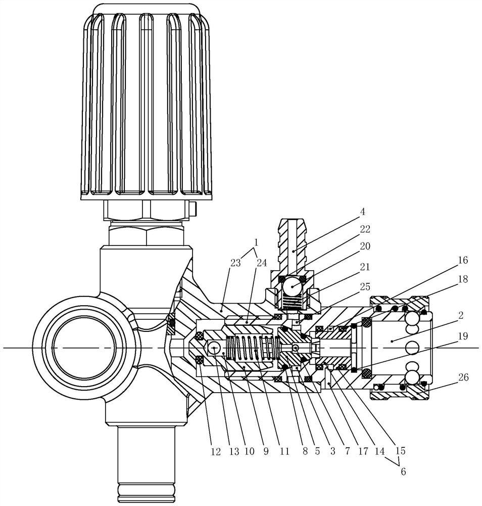
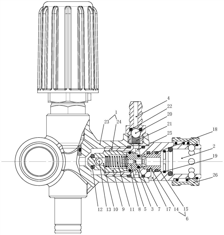
[0021] The present invention will be further described below with specific embodiment, see figure 1 -2:

[0022] A water outlet valve, comprising a valve body 1 with a water outlet hole 2, the water outlet hole 2 is provided with a limit ring surface, and an absorbent groove 3 is provided on the limit ring surface, and the valve body 1 is provided with an inner end and a The sorbent channel 4 connected to the sorbent groove 3 is provided with a one-way component that can prevent the liquid from flowing out, and the water outlet holes 2 located on the inner and outer sides of the limiting ring surface are respectively axially slidably connected with Venturi body 5, and the piston ring sleeve 6 whose inner end can abut against the Venturi body 5, the inner diameter of the inner hole of the Venturi body 5 is larger than the outer end, when the liquid in the outlet end of the water outlet hole 2 is low pressure, The Venturi body 5 slides outwards under the elastic force of the el...


PUM


Abstract

The invention belongs to the technical field of valve bodies, and particularly relates to a water outlet valve which comprises a valve body with a water outlet hole, a limiting ring face is arranged in the water outlet hole, an absorbent groove is formed in the limiting ring face, an absorbent channel is formed in the valve body, a one-way assembly is arranged in the absorbent channel, and a venturi tube body and a piston ring sleeve are connected to the water outlet hole in a sliding mode. The inner end of the inner hole diameter of the venturi tube body is larger than the outer end of the inner hole diameter of the venturi tube body, when liquid is low in pressure, the venturi tube body slides outwards under the elastic piece to abut against and be attached to the limiting ring face, and the absorbent hole communicates with the absorbent groove; when liquid is high in pressure, the piston ring sleeve pushes the venturi tube body to overcome the elastic piece to slide inwards under water pressure. The automatic cleaning agent mixing valve is ingenious in structure and reasonable in design, during low-pressure operation, agent liquid is sucked into the valve body by means of negative pressure generated by flowing of the liquid in the venturi tube body, and then the purpose of automatic cleaning agent mixing is achieved; and during high-pressure cleaning operation, suction and mixing of the agent liquid are automatically stopped, pressure loss caused by an agent suction structure is reduced, and human intervention is not needed in the process.

Description

Technical field: [0001] The invention belongs to the technical field of valve bodies, in particular to a water outlet valve. Background technique: [0002] The existing water outlet valve mainly includes a water inlet port and a water outlet port on the valve body, and the flow or blocking of the liquid between the water inlet port and the water outlet port is adjusted by controlling the valve stem. It has a simple structure and a single function, and The hydraulic pressure of the liquid in the valve body will change due to the change of the size of the pipe, which will lead to the loss of fluid energy. [0003] At the same time, in the kitchen and bathroom for cleaning dishes or related places for cleaning large equipment, it is often necessary to add detergent to the water to form foam water to achieve the purpose of cleaning, but the mixing operation of detergent and water is relatively difficult. Inconvenient and low cleaning efficiency. Invention content: [0004] T...

Claims


Application Information

Patent Timeline
Patent Type & Authority Applications(China)
IPC IPC(8): B05B12/08B05B12/14
CPCB05B12/087B05B12/1418B05B12/1445
Inventor 鲍先启
Owner ZHEJIANG DANAU MASCH CO LTD
Learn More