Rotary cutting machine

A cutting machine, rotary technology, applied in metal processing and other directions, can solve the problems of inability to cut, incomplete cutting, trouble, etc., to achieve the effect of increasing convenience

Inactive Publication Date: 2022-03-01
ANHUI POLYTECHNIC UNIV MECHANICAL & ELECTRICAL COLLEGE
View PDF0 Cites 0 Cited by
  • Summary
  • Abstract
  • Description
  • Claims
  • Application Information

AI Technical Summary

Problems solved by technology

[0004] However, because the rotation is performed with a point as the center of the circle, and the workpiece is fixed in the processing area, this will cause a distance between the cutting machine blade and the workpiece when the rotation changes the angle, and it is easy to cause inability to cut or incomplete cutting. , it is necessary to manually adjust the position of the workpiece, which is troublesome. For this reason, we propose a rotary cutting machine

Method used


Image

  • Rotary cutting machine
  • Rotary cutting machine
  • Rotary cutting machine

Examples


Embodiment 1

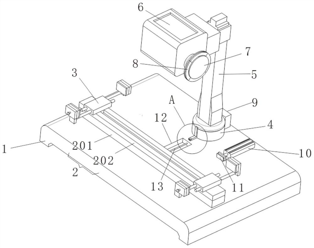
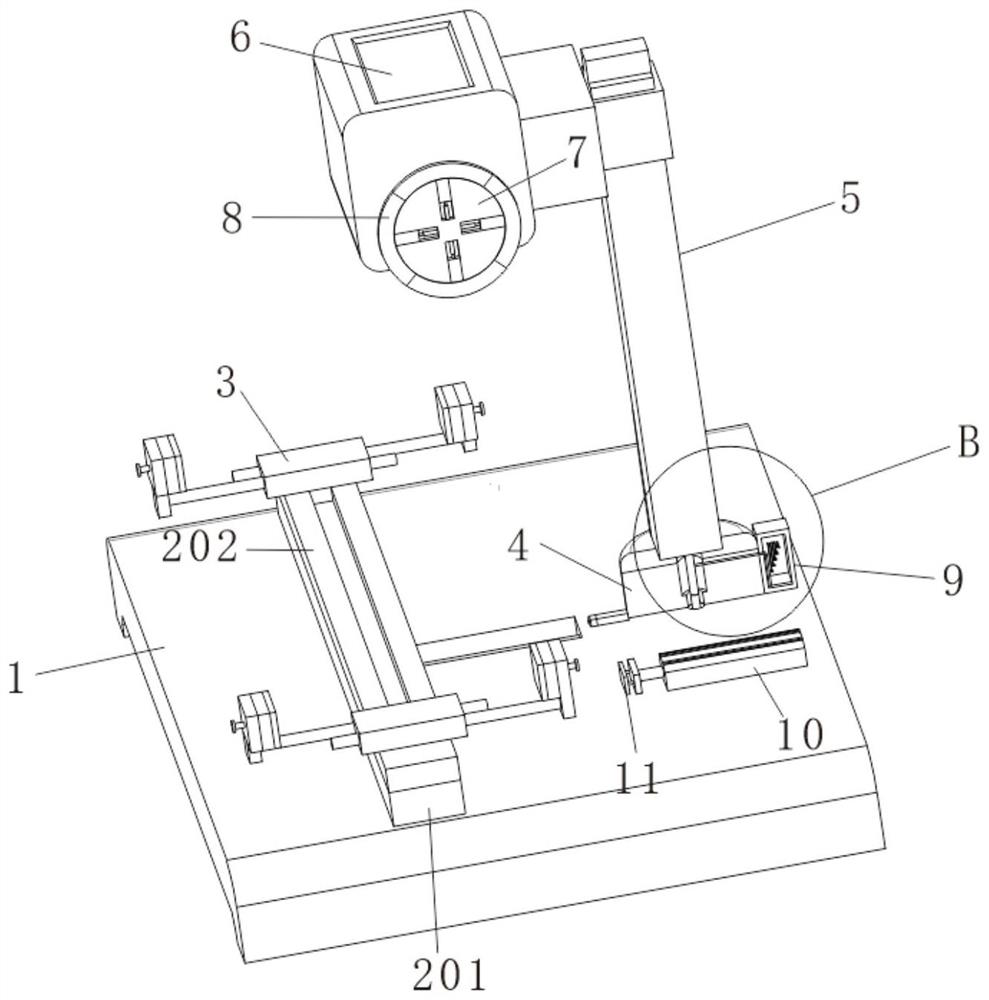
[0028] The present invention provides a technical solution: a rotary cutting machine, please refer to figure 1 with figure 2 , including base 1, mounting base 2 and fixture 3;

[0029] The mounting base 2 is installed on the front side wall of the top of the base 1, and the two sets of fixtures 3 are respectively installed on the left and right side walls of the top of the mounting base 2, and the workpiece is placed above the mounting base 2 and fixed by the clamps 3;

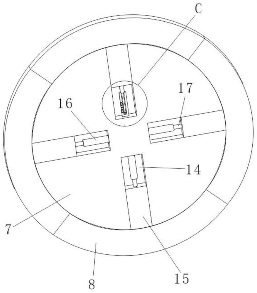
[0030] Base 1 top rear side wall is equipped with support 4, and support 4 top wall is equipped with mounting frame 5, and mounting frame 5 front side walls are equipped with cutting equipment 6, and cutting equipment 6 can slide on mounting frame 5 front side walls, with To move up and down with the blade 8 to realize the cutting and processing of the workpiece, the output shaft on the right side of the cutting device 6 is equipped with a connecting plate 7, and the outer wall of the connecting plate 7 is m...

Embodiment 2

[0035] see figure 1, on the basis of Embodiment 1, a guide groove 12 is provided on the top wall of the base 1, a guide block is installed on the bottom wall of the mounting seat 2, and the guide block is slidably inserted into the inner cavity of the guide groove 12, and the outer wall of the guide block and the rotating rod A connecting rope 13 is installed between the 18 outer walls, and the cutting device 6 rotates so that when the rotating rod 18 is rotated, the connecting rope 13 will also be wound on the outer wall of the rotating rod 18, so that the guide block slides in the inner cavity of the guide groove 12, Pull the mounting seat 2 backward to reduce the distance between the mounting seat 2 and the support 4, and make the workpiece move closer to the blade 8, further ensuring that the cutting machine after rotation can directly process the workpiece, and the rear side of the guide block The wall is equipped with an installation sleeve, and the front end of the conn...

Embodiment 3

[0040] see figure 1 with figure 2 , on the basis of Embodiment 1, the mounting seat 2 includes a mounting plate 201 connected to the top wall of the guide block, the top wall of the mounting plate 201 is provided with a slot, and the top of the slotted cavity is slidingly inserted with a moving seat 202, and the moving seat 202 It is fixed on the top of the mounting plate 201 by bolts, and the height of the fixture 3 can be adjusted by sliding the movable seat 202 in the grooved inner cavity. The guide chute, the bottom end of the clamp 3 is slid and inserted into the inner cavity of the guide chute, so that the distance between the two sets of clamps 3 can be adjusted;

[0041] Compared with the first embodiment, components such as the mounting plate 201 and the moving seat 202 are added, so that the height of the clamps 3 and the distance between the clamps 3 can be adjusted.

[0042] Working principle: Put the workpiece on the top of the mounting base 2 and fix it by the...


PUM


Abstract

The invention discloses a rotary cutting machine in the technical field of cutting machines, which comprises a base, a mounting seat and a clamp, the mounting seat is mounted on the front side wall of the top of the base, a mounting frame is mounted on the top wall of a support, cutting equipment is mounted on the front side wall of the mounting frame, and a connecting disc is mounted on an output shaft on the right side of the cutting equipment. According to the device, cutting equipment rotates, so that a support rotates above a supporting seat, a rotating rod rotates in an inner cavity of a hole, a pull rope is wound around the outer wall of the rotating rod, a pressing plate is driven to move upwards, a touch switch below a supporting block is pressed, an electromagnet is powered on to be attracted to a magnetic block, and the blade is driven to rotate through the rotating rod; the magnetic block is completely moved into the inner cavity of the placing groove, so that the stopping block is blocked and disappears, and when the connecting disc drives the blade to rotate, the coverage range of the blade is enlarged, it is ensured that the rotating blade can still cut a machined part, the machined part does not need to be moved again, and the use convenience of the cutting machine is improved.

Description

technical field [0001] The invention relates to the technical field of cutting machines, in particular to a rotary cutting machine. Background technique [0002] Cutting machine is a kind of cutting equipment, which is mainly used for cutting and processing workpieces. [0003] When the existing cutting machine is in use, in order to increase the convenience of cutting, the existing cutting machine can generally rotate to change its own angle, and cut the workpiece at different angles; [0004] However, because the rotation is performed with a point as the center of the circle, and the workpiece is fixed in the processing area, this will cause a distance between the cutting machine blade and the workpiece when the rotation changes the angle, and it is easy to cause inability to cut or incomplete cutting. , it is necessary to manually adjust the position of the workpiece, which is troublesome. For this reason, we propose a rotary cutting machine. Contents of the invention ...

Claims


Application Information

Patent Timeline
IPC IPC(8): B26D1/14B26D5/08B26D7/02B26D7/00
CPCB26D1/14B26D5/086B26D7/02B26D7/00
Inventor 范尤瑞
Owner ANHUI POLYTECHNIC UNIV MECHANICAL & ELECTRICAL COLLEGE
Why Eureka
Try Eureka