
Washing machine speed reduction clutch device, washing machine and control method of washing machine

A technology for clutch devices and washing machines, which is applied to the control devices of washing machines, washing devices, and other washing machines. It can solve the problems of poor meshing stability of the clutch mechanism, complex structure of the deceleration clutch device, and inability to lock the clutch mechanism. Clothes washing effect, improvement of variety, high reliability effect

Pending Publication Date: 2022-03-01
QINGDAO HAIER WASHING MASCH CO LTD +1
View PDF2 Cites 0 Cited by
  • Summary
  • Abstract
  • Description
  • Claims
  • Application Information

AI Technical Summary

Problems solved by technology

The first method above has the disadvantages of complex structure of the deceleration clutch device, difficult installation and complicated control method, and the disadvantage of high cost of the driving motor with bidirectional power output in the second method
[0007] In addition, the deceleration clutch device is used to realize the switching of various washing modes of the washing machine. Since the clutch mechanisms of the deceleration clutch device need to be kept in the meshing states corresponding to the various laundry modes, the existing multi-stroke motor-driven clutch mechanism is used to realize various washing modes. The meshing state corresponding to the laundry mode is switched, but the multi-stroke motor cannot lock the clutch mechanism, and the stability of the clutch mechanism meshing is not good

Method used


Image

  • Washing machine speed reduction clutch device, washing machine and control method of washing machine
  • Washing machine speed reduction clutch device, washing machine and control method of washing machine
  • Washing machine speed reduction clutch device, washing machine and control method of washing machine

Examples


Embodiment Construction

[0044] A deceleration clutch device for a washing machine, a washing machine and a control method thereof of the present invention are described in detail below in conjunction with the accompanying drawings:

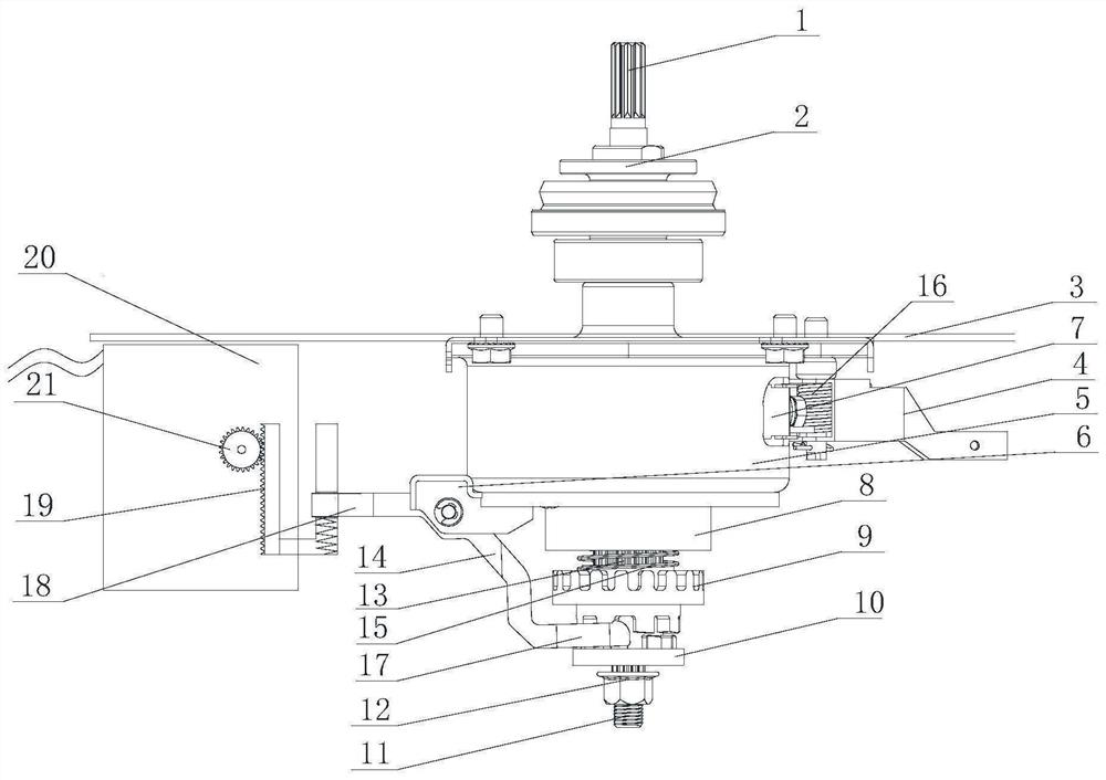
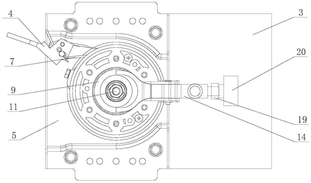
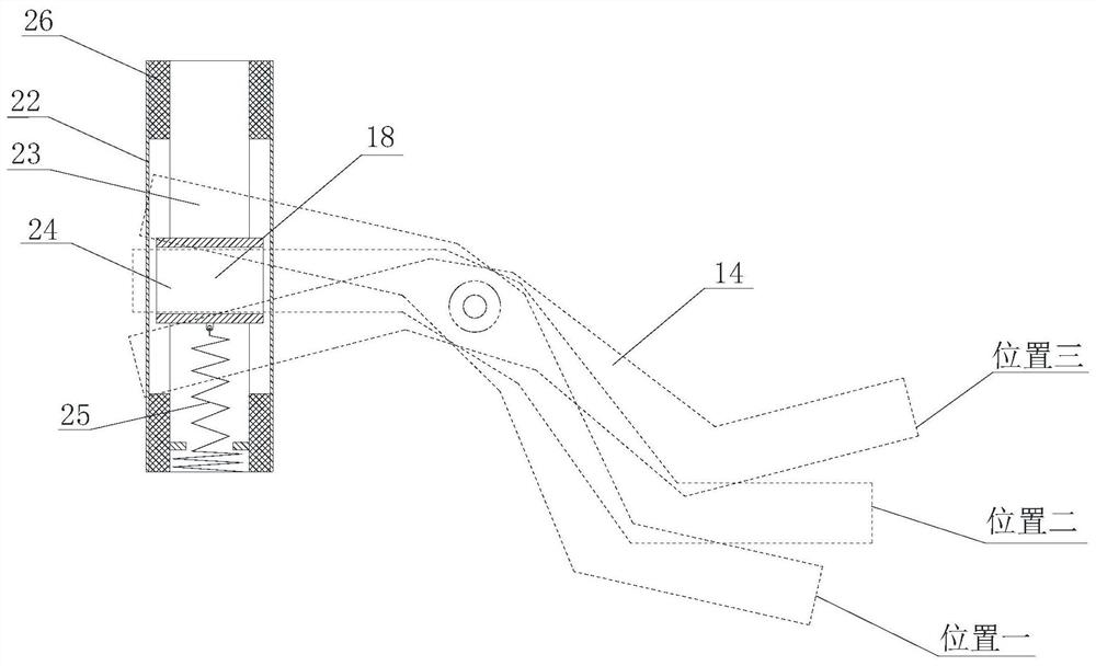
[0045] Such as Figure 1-Figure 6 As shown, this embodiment provides a deceleration clutch device for a washing machine, including a clutch mechanism. The clutch mechanism includes a clutch sleeve 9 that can reciprocate for clutch switching and a shift fork assembly that drives the movement of the clutch sleeve 9. The shift fork assembly includes a shift Fork 14 and shift fork driving device, one end of shift fork 14 is fork connected on the clutch sleeve 9, shift fork driving device includes power part 20 and rack and pinion transmission mechanism, the rotation output end of power part 20 is connected with the gear and rack transmission mechanism The other end of the shift fork 14 is connected by transmission; the power component 20 drives the shift fork to move the clu...


PUM


Abstract

The invention provides a washing machine speed reduction clutch device, a washing machine and a control method thereof.The washing machine speed reduction clutch device comprises a clutch mechanism, the clutch mechanism comprises a clutch sleeve and a shifting fork assembly, the clutch sleeve can reciprocate to conduct clutch switching, the shifting fork assembly drives the clutch sleeve to move, and the shifting fork assembly comprises a shifting fork and a shifting fork driving device; one end of the shifting fork is connected to the clutch sleeve in a forked mode, the shifting fork driving device comprises a power component and a gear and rack transmission mechanism, and the rotating output end of the power component is in transmission connection with the other end of the shifting fork through the gear and rack transmission mechanism. And the power part drives the shifting fork to shift the clutch sleeve to do reciprocating motion through the gear and rack transmission mechanism to perform clutch switching. The rotation output of the power part of the washing machine speed reduction clutch device is converted into reciprocating motion in the vertical direction through the gear and rack transmission mechanism to drive the shifting fork to stir the clutch sleeve to do reciprocating motion for clutch switching, and the stability of the washing machine speed reduction clutch device in the working process is improved.

Description

technical field [0001] The invention relates to the technical field of laundry equipment, in particular to a deceleration clutch device for a washing machine, a washing machine and a control method thereof. Background technique [0002] Washing machine, as a kind of household appliance, gradually becomes an indispensable part in people's life, and fully automatic pulsator washing machine, as a kind of main washing machine type, its scope of application is also more and more extensive. The working mode of the existing fully automatic pulsator washing machine is generally as follows: when washing and rinsing, the driving device drives the pulsator of the washing machine to forward and reverse through the deceleration clutch device; Synchronous high-speed rotation. [0003] However, with the rapid development of science and technology, the existing fully automatic pulsator washing machine relying solely on the pulsator to stir the water flow is more and more limited in improvi...

Claims


Application Information

Patent Timeline
IPC IPC(8): D06F37/30D06F37/40D06F33/00D06F105/46
CPCD06F37/30D06F37/40D06F33/00D06F2105/46
Inventor 张刚金刘尊安刘庆徐杰姜同春
Owner QINGDAO HAIER WASHING MASCH CO LTD
Learn More