Eureka AIR delivers breakthrough ideas for toughest innovation challenges, trusted by R&D personnel around the world.

Construction method for subsection sinking of underground building composed of connecting piles

A technology for underground buildings and connecting piles, which is applied to buildings, underwater structures, artificial islands, etc., can solve the problems of uncontrolled sinking speed, long construction period, high cost, etc. Simple construction effect

Pending Publication Date: 2022-03-01
王树生
View PDF0 Cites 0 Cited by
  • Summary
  • Abstract
  • Description
  • Claims
  • Application Information

AI Technical Summary

Problems solved by technology

[0002] Existing large-scale underground buildings are often constructed by the open-cut method. The open-cut method needs to excavate the foundation pit first for support and precipitation, and then pour or assemble the underground building in the foundation pit. The process is complicated, the cost is expensive, and the construction period is long. to the surrounding high-rise buildings
[0003] The existing technical scheme for the overall sinking of underground buildings relies on its own weight to sink, and its own weight is all pressed on the bottom chain knife. The chain knife is easy to break and the driving power is greatly increased; the descent is prone to tilt, and it is difficult to correct the deviation; the descent speed cannot be controlled That is, the amount of feed, the sinking speed is out of control, and the cutter head is easy to wear

Method used


Image

  • Construction method for subsection sinking of underground building composed of connecting piles
  • Construction method for subsection sinking of underground building composed of connecting piles
  • Construction method for subsection sinking of underground building composed of connecting piles

Examples


Embodiment Construction

[0028] The technical solutions in the embodiments of the present invention will be clearly and completely described below in conjunction with the accompanying drawings in the embodiments of the present invention. Obviously, the described embodiments are only some of the embodiments of the present invention, not all of them. Based on The embodiments of the present invention and all other embodiments obtained by persons of ordinary skill in the art without making creative efforts belong to the protection scope of the present invention.

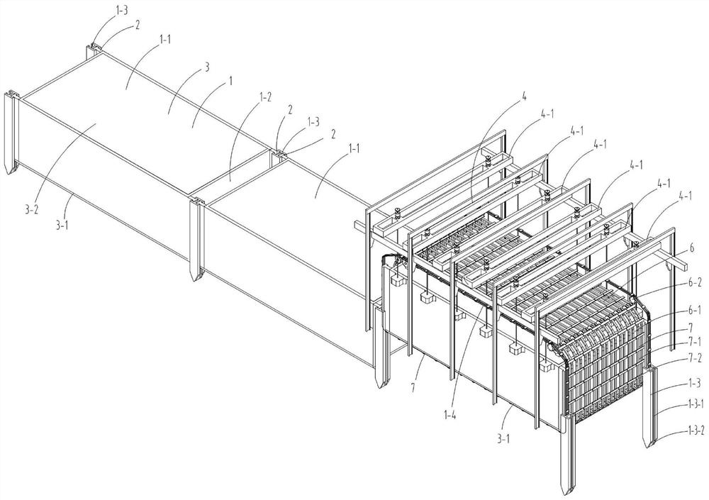
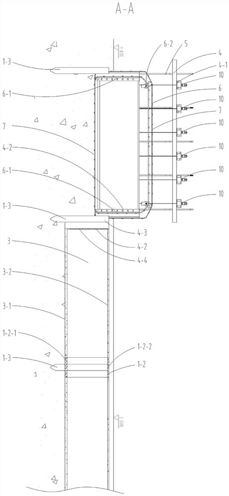
[0029] see Figure 1-10 In the embodiment of the present invention, such as figure 1 As shown, building 1 is an underground comprehensive pipe gallery, including several pipe joints 1-1, interfaces 1-2, connecting piles 1-3 and construction devices 1-4, and pipe joints 1-1 include vertical The boss 2 and the pipe body 3, the construction device 1-4 includes a pipe joint construction device 4 and a pile construction device 5, the interface 1-2 i...


PUM


Abstract

The invention discloses a construction method for subsection sinking of an underground building composed of connecting piles, and relates to the technical field of underground building construction.The building located underground comprises a plurality of pipe joints, connectors, the connecting piles and a construction device, and each pipe joint comprises a vertical boss located on the side portion of the two ends and a pipe body; the construction device comprises a pipe joint construction device and a pile construction device, the connector is located at the connecting position of two adjacent pipe bodies and located between two transversely-arranged connecting piles, the shape of an inner cavity of the section of the connector is the same as that of an inner cavity of the section of each pipe body, the connector is constructed after adjacent pipe joints and connecting piles are completed, each connecting pile comprises a groove, and a boss is embedded into the groove. The pipe joint construction device comprises an excavating device and a hanging device located at the top of a pipe joint, the excavating device comprises end racks located at the two ends, a chain cutter arranged longitudinally and a driving device installed above a pipe body, the chain cutter comprises a chain and a cutter installed on the chain, and the chain cutter wraps the pipe body through the end racks.

Description

technical field [0001] The invention relates to the technical field of underground building construction, in particular to a construction method for subsidence of an underground building composed of connecting piles. Background technique [0002] Existing large-scale underground buildings are often constructed by the open-cut method. The open-cut method needs to excavate the foundation pit first for support and precipitation, and then pour or assemble the underground building in the foundation pit. The process is complicated, the cost is expensive, and the construction period is long. There is a larger impact on the surrounding high-rise buildings. [0003] The existing technical scheme for the overall sinking of underground buildings relies on its own weight to sink, and its own weight is all pressed on the bottom chain knife. The chain knife is easy to break and the driving power is greatly increased; the descent is prone to tilt, and it is difficult to correct the deviati...

Claims


Application Information

Patent Timeline
Patent Type & Authority Applications(China)
IPC IPC(8): E02D5/52E02D15/08E02D29/055E02F5/20E02F3/08E02F3/14
CPCE02D5/526E02D15/08E02D29/055E02F5/20E02F3/08E02F3/143E02F3/145
Inventor 王树生
Owner 王树生
Why Eureka
Eureka Blog
Learn More